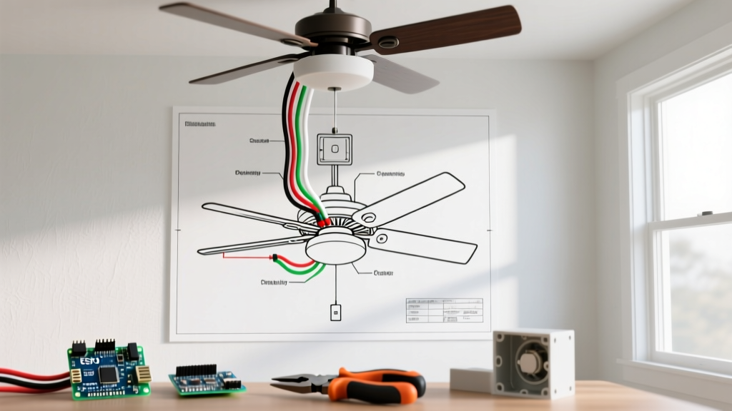

Pre-Installation: Assessing Your Electrical Box and Circuit
Before you even look at a wiring diagram for ceiling fan units, the most critical step in your installation planning is verifying your ceiling junction box. According to the National Electrical Code (NEC) Article 314.27(D), any outlet box supporting a ceiling fan must be specifically listed and marked by the manufacturer as suitable for fan support. Standard light fixture boxes are only rated to hold up to 50 pounds and will fail under the dynamic vibration of a spinning fan motor.
NEC Code Warning: Never mount a ceiling fan to a standard 'old work' drywall box or a standard octagonal light box. You must use a fan-rated box, such as the Raco 4-inch Fan-Rated Octagon Box (Model #568), which is braced directly to the ceiling joist and rated for up to 70 pounds of dynamic weight.
Next, verify your circuit capacity. Most modern ceiling fans with integrated LED light kits draw less than 1.5 amps total. A standard 15-amp circuit using 14 AWG NM-B (Romex) cable is more than sufficient. However, if your fan circuit shares a breaker with high-draw bathroom receptacles or window air conditioners, you must calculate the continuous load to ensure you do not exceed 80% of the breaker's capacity (12 amps on a 15A breaker).
Decoding the Standard Wiring Diagram for Ceiling Fan Units
When you unbox a new ceiling fan from brands like Hunter, Minka-Aire, or Hampton Bay, the included wiring diagram for ceiling fan connections will feature a standardized color-coding system. Understanding this mapping is essential before stripping any wires.
| Wire Color (Fan) | Function | Connects To (House Wiring) | Wire Nut Size (Typical) |
|---|---|---|---|
| Black | Fan Motor Hot (Load 1) | Switched Hot (Black or Red) | Yellow (Ideal 72B) |
| Blue | Light Kit Hot (Load 2) | Switched Hot (Black or Red) | Yellow (Ideal 72B) |
| White | Neutral (Common Return) | House Neutral (White) | Yellow or Red |
| Green / Bare Copper | Equipment Ground | House Ground (Bare/Green) | Green (Ideal 83B) |
Note: If your fan includes a remote control receiver module, the receiver will wire inline between the house power and the fan's native wires. Always follow the receiver's specific schematic, as it often requires connecting the fan's blue and black wires directly to the receiver's output leads.
Switch Configurations: Planning Your Wall Control
The wiring diagram for ceiling fan setups changes drastically depending on whether you want to control the fan and light independently from the wall, or rely on pull chains. This decision must be made before running cable.
Scenario A: Single Wall Switch (Pull Chain Control)
If you are replacing an existing light fixture with a fan and only have a 2-wire cable (14/2 or 12/2 NM-B) running from the switch to the ceiling, you are limited to a single switch configuration. In this setup, the wall switch controls power to both the fan and the light simultaneously. You will connect both the Black (fan) and Blue (light) wires from the ceiling fan to the single Switched Hot wire coming from the house. Speed and light dimming must then be controlled via the fan's physical pull chains or a handheld remote.
Scenario B: Dual Wall Switch (Independent Control)
For independent wall control of the fan motor and the light kit, you must run a 3-wire cable (14/3 or 12/3 NM-B) from a double-pole wall switch to the ceiling box. The wiring diagram for ceiling fan dual-switch setups utilizes the extra red wire found in 14/3 Romex.
- Black House Wire: Connects to the Black Fan Wire (Fan Motor).
- Red House Wire: Connects to the Blue Fan Wire (Light Kit).
- White House Wire: Connects to the White Fan Wire (Neutral).
- Bare House Wire: Connects to the Green Fan Wire (Ground).
This configuration requires a dual rocker switch (such as the Leviton 5241) where one switch is rated for motor loads (usually 5A) and the other for lighting.
Smart Fan Controls and 2026 Matter Protocol Integration
As of 2026, the integration of smart home ecosystems has shifted heavily toward the Matter-over-Thread protocol. If you are planning to install a smart fan controller like the Lutron Caseta Fan Control (Model PD-FSQNX) or a newer Matter-compatible smart switch, your wiring plan must account for a neutral wire at the switch box.
Older homes often only have a 2-wire switch loop (hot and switched hot) at the wall, with the neutral capped off in the ceiling box. Smart fan controllers require a continuous 120V power supply to keep their internal radios (Wi-Fi, Zigbee, or Thread) active. If your switch box lacks a neutral wire, you have two options:
- Pull New Cable: Replace the 2-wire switch loop with 14/3 NM-B to bring a neutral down to the switch box.
- Use a Canopy Module: Install a smart receiver module (like the Bond Bridge receiver or a Sonoff iFan04) up in the ceiling canopy where the neutral is readily available, and use a wireless remote or smart button on the wall.
For comprehensive guidelines on energy-efficient fan operation and smart home integration, refer to the EPA's Energy Star Ceiling Fan specifications, which detail the airflow efficiency (CFM/Watt) requirements for modern smart-enabled units.
Execution: Wire Stripping, Torque, and Safety
A flawless wiring diagram for ceiling fan installation means nothing if the physical terminations are poor. Loose connections are the primary cause of arcing, which can lead to electrical fires. Follow these precise execution steps:
- Stripping: Use precision wire strippers (like the Klein Tools 11055) to strip exactly 3/4 inch of insulation from 14 AWG solid copper wire. Stripping too little results in the wire nut gripping the insulation; stripping too much exposes bare copper outside the nut, creating a shock hazard.
- Alignment: Hold the wires to be spliced perfectly parallel. Do not pre-twist solid wires together before applying the wire nut; the internal steel coil of a high-quality wire nut (such as Ideal SureWire) is designed to bite into the copper and twist them together simultaneously.
- Torque: Twist the wire nut clockwise until you feel the wires twist together inside the connector and the nut clicks or stops firmly. Give each wire a gentle tug test to ensure it does not pull out.
- Grounding Pigtails: If the ceiling box is metal, you must ground the box itself in addition to the fan. Use a green grounding screw (10-32 thread) and a bare copper pigtail to bond the box to the main ground wire bundle.
Always verify your work with a non-contact voltage tester and a multimeter before energizing the circuit. For foundational safety practices, consult the Electrical Safety Foundation International (ESFI) home safety guidelines to ensure your workspace and tools meet modern safety standards.
Troubleshooting Common Wiring Failures
Even with a correct wiring diagram for ceiling fan setups, DIYers frequently encounter specific edge cases. Here is how to diagnose and resolve them:
1. The Fan Motor Hums but Does Not Spin
The Cause: This almost always occurs when a standard incandescent dimmer switch is wired to control the fan motor. Dimmers chop the AC sine wave to reduce voltage, which destroys the torque of an induction motor and causes a loud 60Hz hum.
The Fix: Ensure the wall switch controlling the black (fan) wire is a standard single-pole toggle switch or a dedicated fan speed control (which uses stepped capacitors, not phase-cutting dimmers). Never put a fan motor on a lighting dimmer.
2. The LED Light Kit Flickers or Strobes
The Cause: A loose neutral connection or an incompatible dimmer. Integrated LED fans require a steady 120V supply. If the white neutral wire is loose at the ceiling canopy or the switch box, the return path is interrupted, causing micro-strobing.
The Fix: Turn off the breaker, lower the canopy, and check the white-to-white wire nut connection. Ensure no stray strands of ground wire are touching the neutral bundle. If using a wall dimmer for the light kit, ensure it is an ELV (Electronic Low Voltage) or CL (Cassetta LED) dimmer specifically rated for LED loads, such as the Lutron Diva DVCL-153P.
3. The Fan Spins in Reverse (Updraft)
The Cause: While not strictly a wiring error, many installers panic when the fan pulls air up. This is usually controlled by a physical toggle switch on the fan motor housing, or a button on the remote control.
The Fix: Locate the directional switch above the fan blades. For optimal cooling in the summer, the fan should spin counter-clockwise (pushing air down). For winter, clockwise at low speed pulls cold air up and pushes warm ceiling air down the walls.
By meticulously planning your junction box support, selecting the correct NM-B cable for your desired switch configuration, and adhering strictly to the manufacturer's wiring diagram for ceiling fan termination, you ensure a safe, quiet, and code-compliant installation that will last for decades. Always adhere to the latest NFPA 70 National Electrical Code updates and pull a local permit if your municipality requires it for new circuit installations.