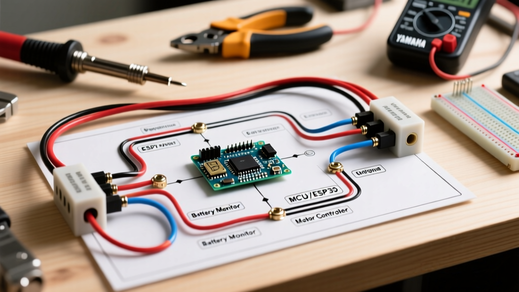

Architectural Overview: Yamaha Drive (G29) 48V AC Systems
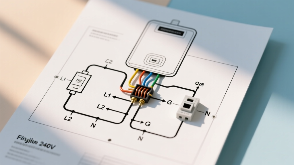
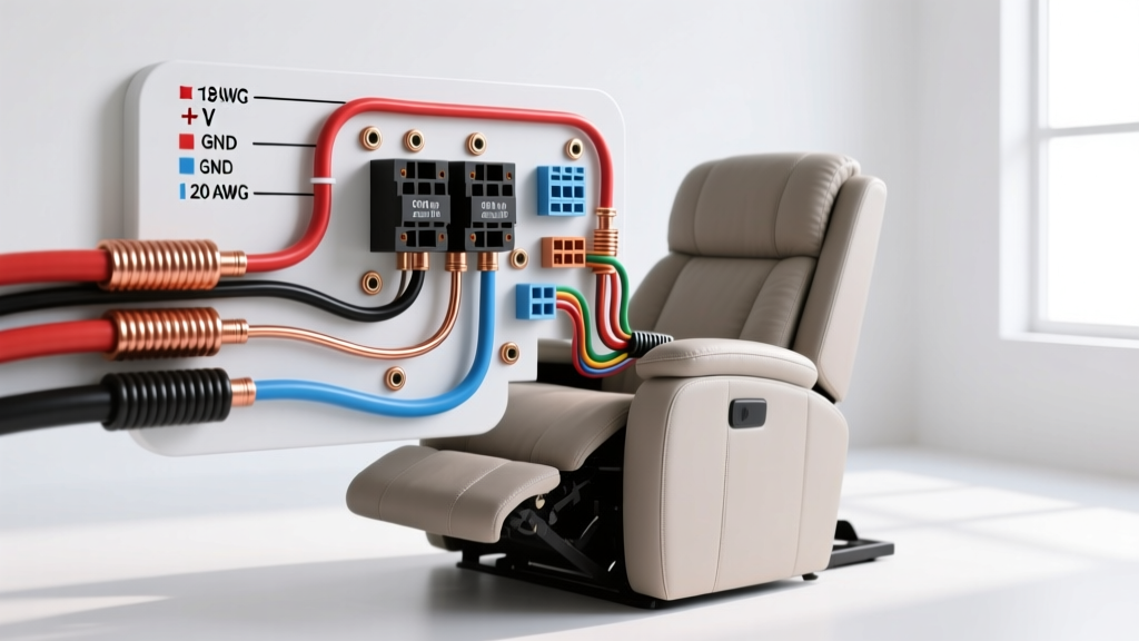
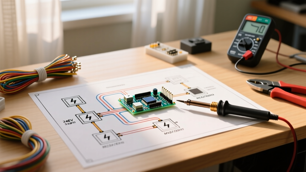
Planning a complete rewire or custom accessory integration for a Yamaha golf cart requires a fundamental understanding of its electrical architecture. Unlike older DC-motor platforms (such as the G16 or G22), the modern Yamaha Drive (G29) series utilizes a sophisticated 48V AC induction motor paired with a high-frequency motor controller. When referencing a wiring diagram for a Yamaha golf cart, technicians must bifurcate the system into two distinct circuits: the high-current traction circuit and the low-current logic/sensor circuit.
As of 2026, the aftermarket has heavily shifted toward drop-in 48V Lithium Iron Phosphate (LiFePO4) battery banks, such as the Allied Lithium 105Ah or EcoBattery systems. These modern power sources alter the traditional wiring diagram by eliminating the heavy 2 AWG series-link cables between six individual 8V lead-acid batteries, replacing them with a single unified 2 AWG positive and negative output. This reduces voltage drop and simplifies the main power routing to the solenoid.
Critical Safety Protocol
Before consulting the schematic or disconnecting any terminals, you must engage the Run/Tow switch located under the passenger seat. Setting this switch to TOW disconnects the logic power from the controller, preventing catastrophic regenerative braking feedback loops that can fry the controller's internal MOSFETs if a circuit is broken while the motor is spinning.
Decoding the Wiring Diagram: High-Current Traction Circuit
The traction circuit handles the raw amperage required to move the vehicle. In a standard Yamaha G29 AC wiring diagram, the main power flows from the battery pack's positive terminal to the heavy-duty main solenoid, then into the controller's B+ terminal. The return path flows from the controller's B- terminal directly to the battery pack's negative busbar.
Wire Gauge & Torque Specification Matrix
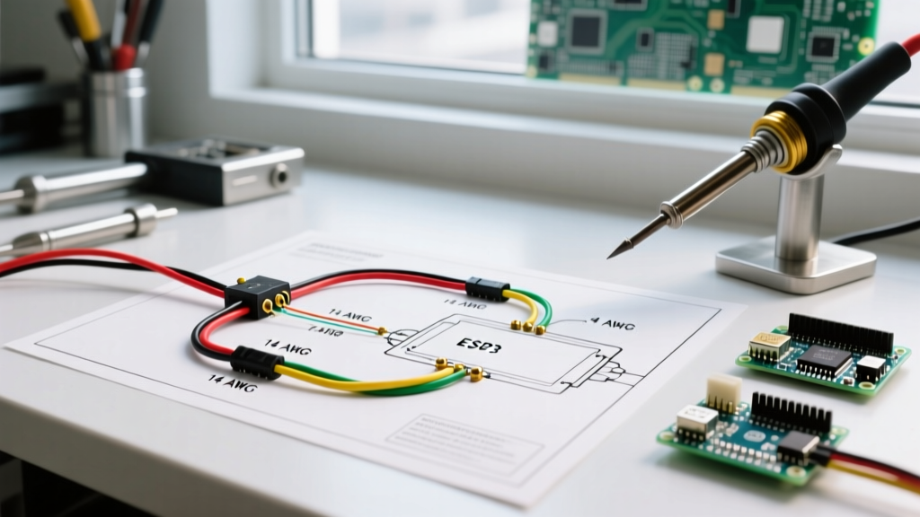
Adhering to proper American Wire Gauge (AWG) sizing and terminal torque specifications is non-negotiable. Loose high-current connections generate arcing, leading to melted terminal blocks and potential electrical fires. The following matrix outlines the OEM specifications for the 48V AC platform:
| Circuit Path | Wire Gauge (AWG) | Terminal Type | Torque Spec |
|---|---|---|---|
| Battery (+) to Solenoid Input | 2 AWG | 5/16" Ring, Heat Shrink | 120 in-lbs |
| Solenoid Output to Controller B+ | 4 AWG | 5/16" Ring, Heat Shrink | 100 in-lbs |
| Controller B- to Battery (-) | 2 AWG | 5/16" Ring, Heat Shrink | 120 in-lbs |
| Controller to Motor (Phase U, V, W) | 4 AWG | 10mm Ring, Marine Shrink | 80 in-lbs |
Note: For wire ampacity baselines and DC voltage drop calculations, technicians should cross-reference standard electrical codes. Adaptations of NFPA 70 (NEC) Table 310.16 are frequently used by low-speed vehicle (LSV) engineers to ensure 4 AWG and 2 AWG cables can handle the 300A+ peak surge currents of an AC motor controller without exceeding thermal limits.
The Logic Circuit: Pre-Charge, MCOR, and Sensors
The most common point of failure during a DIY installation or harness replacement occurs in the low-current logic circuit. This circuit operates on 48V stepped down to 12V/5V logic, managing the solenoid engagement, throttle input, and motor position sensing.
The Pre-Charge Circuit: Protecting the Controller
When you press the accelerator, the Yamaha wiring diagram routes 48V through the ignition switch and the forward/reverse micro-switches to energize the solenoid coil. However, before the main solenoid contacts close, a pre-charge circuit must activate. This circuit utilizes a 400-ohm, 10-watt ceramic resistor wired in parallel across the main solenoid's large terminals.
- Purpose: It slowly charges the massive internal capacitors of the AC motor controller. Without it, the instantaneous inrush current when the solenoid closes would weld the solenoid contacts together and potentially blow the controller's internal DC bus capacitors.
- Installation Tip: Ensure the pre-charge resistor is mounted in a high-airflow area. It generates significant heat during the milliseconds it takes to charge the capacitors.
MCOR (Motor Controller Output Regulator) Integration
Yamaha abandoned the traditional inductive throttle sensor (ITS) found on older gas carts in favor of the MCOR, a non-contact Hall-effect sensor that translates pedal travel into a variable voltage signal (typically 0.8V to 3.6V) for the controller. When planning your wiring layout, the MCOR requires a dedicated 3-wire or 4-wire shielded harness. Route this harness at least 4 inches away from the high-current phase wires (U, V, W) to prevent electromagnetic interference (EMI), which manifests as erratic acceleration or 'ghost' throttle faults.
2026 Lithium Conversion Wiring Adjustments
If your installation plan involves upgrading to a modern lithium battery bank, the standard Yamaha wiring diagram requires specific modifications. According to battery manufacturing standards outlined by Battery Council International (BCI), lithium BMS (Battery Management System) protocols require specific communication wiring that lead-acid setups do not use.
Expert Insight: When wiring a 48V Lithium pack to a Yamaha G29, you must install a lithium-specific solenoid eliminator or a heavy-duty solid-state relay. Standard mechanical Albright SW200 solenoids can suffer from contact bounce, which some sensitive lithium BMS units interpret as a short circuit, causing the battery to shut down mid-drive. Upgrading to a Curtis 701 solid-state contactor (approx. $110 in 2026) ensures a bounce-free connection.
Step-by-Step Installation Planning Flow
To execute a flawless installation, follow this sequential workflow. Do not deviate from the order of operations, as back-feeding voltage into the controller logic pins before the high-current ground is secured can destroy the microprocessor.
- Chassis Grounding: Establish a dedicated 4 AWG ground strap from the motor casing to the main battery negative busbar. Do not rely on the motor mount bolts for grounding; paint and powder coating will cause high-resistance ground faults.
- High-Current Negative Routing: Connect the Controller B- to the battery negative. Verify continuity with a multimeter before proceeding.
- High-Current Positive Routing: Connect the battery positive to the solenoid input, and the solenoid output to the Controller B+. Leave the main battery disconnect OFF.
- Motor Phase Wiring: Connect the U, V, and W phase wires. The sequence does not matter for initial testing; if the motor spins in reverse, simply swap any two of the three phase wires to reverse the rotation.
- Logic & Sensor Harness: Plug in the 16-pin and 35-pin Deutsch/Molex connectors to the controller. Ensure the locking tabs audibly click. Apply dielectric grease (e.g., MG Chemicals 846) to prevent moisture ingress.
- Final Energization: Turn on the main battery breaker, set the Run/Tow switch to RUN, and turn the key to ON. You should hear a distinct 'click' from the solenoid and a secondary click from the motor brake releasing.
Common Failure Modes & Edge Cases
Even with a perfect wiring diagram, environmental and mechanical edge cases can derail an installation. Be prepared to troubleshoot the following scenarios:
- Solenoid Chatter: If the solenoid rapidly clicks on and off when the pedal is pressed, inspect the 12V step-down converter. Yamaha carts use a voltage reducer to power accessories; if it is failing, it can drag down the logic voltage below the controller's 35V minimum threshold, causing it to reset and drop the solenoid signal.
- Regenerative Braking Over-Voltage: When descending steep hills, the AC motor acts as a generator. If the battery bank is fully charged (especially common with lithium BMS limits), the controller has nowhere to push the regenerative current. This triggers an over-voltage fault (Code 4-3 on Curtis controllers). Planning for a high-wattage braking resistor or ensuring your lithium BMS supports active regenerative absorption is critical for hilly terrain.
- Encoder Signal Loss: The Yamaha AC motor relies on a 3-phase Hall effect encoder to determine rotor position. If the 5-pin encoder connector is exposed to water without marine-grade heat shrink, corrosion will cause the controller to lose motor timing, resulting in a violent shuddering sensation upon acceleration.
Authoritative References & Component Sourcing
For advanced diagnostics, programming the controller, or sourcing OEM-spec replacement parts, rely on verified technical documentation rather than generic forum hearsay. The Curtis Instruments Motor Speed Controllers documentation portal provides exhaustive PDF manuals for the 1238AC and 1236AC controllers used in Yamaha platforms, detailing exact pinout schematics, fault code matrices, and VCL (Vehicle Control Language) programming parameters. Always cross-reference your cart's specific serial number prefix (e.g., JW2 for 2012 models) against the Yamaha factory service manual to account for mid-year harness revisions.