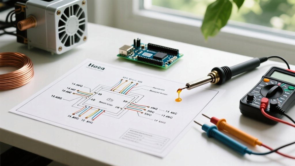

Anatomy of a Heat Pump Electrical Wiring Diagram
Understanding a heat pump electrical wiring diagram is fundamentally different from deciphering a standard gas furnace or straight air conditioning schematic. Modern high-efficiency split-system heat pumps, such as the 2026 Bosch IDS 3.0 or Trane XV20i variable-speed models, integrate complex inverter logic, multi-stage reversing valves, and advanced defrost boards. For DIY enthusiasts and junior technicians, misinterpreting these schematics can lead to catastrophic compressor failure, blown control boards, or severe electrical hazards.
According to the National Fire Protection Association (NFPA 70), HVAC installations must strictly adhere to Article 440 of the National Electrical Code (NEC), which governs air-conditioning and refrigerating equipment. In 2026, local jurisdictions are heavily enforcing updated GFCI and AFCI protection requirements for outdoor disconnects, making it imperative to understand not just the internal wiring, but the feeder circuit design.
Safety Warning: Before opening any condenser or air handler access panel, verify power is disconnected at the main breaker and the outdoor disconnect switch. Use a Category III or IV multimeter to confirm zero voltage across L1 and L2. Capacitors can hold lethal charges even after power is removed; always use a 20,000-ohm, 5-watt resistor to safely bleed the terminals.
1. The High-Voltage Power Circuit (240V)
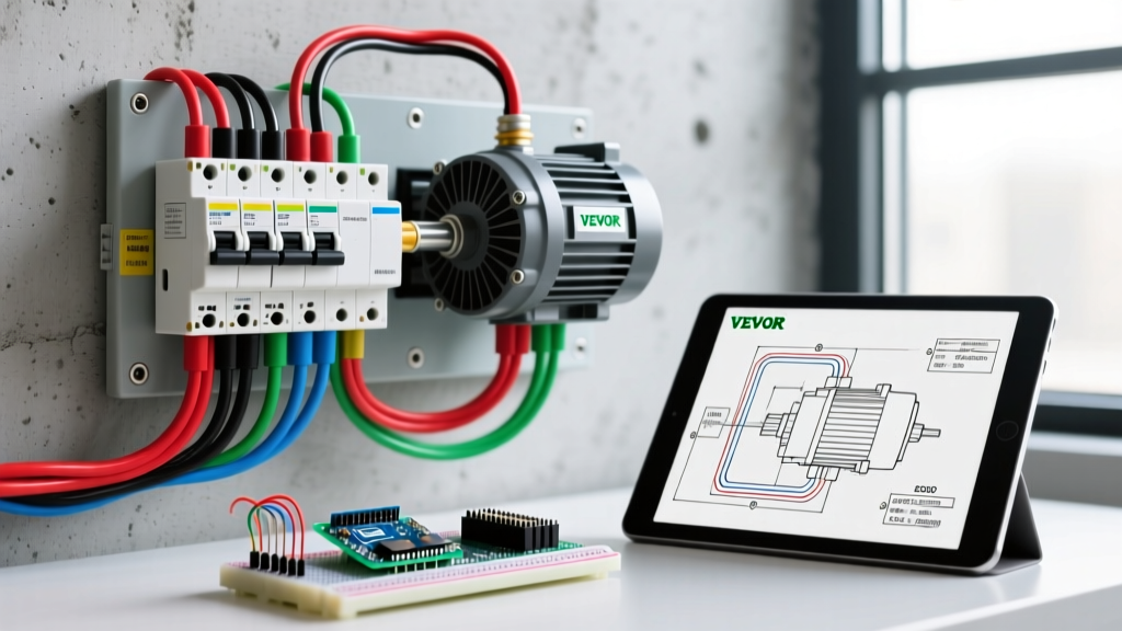
The high-voltage side of the diagram details the path from the outdoor disconnect to the compressor contactor and the indoor air handler. In a standard residential 2-ton to 4-ton heat pump, you will be working with 240V single-phase power. The schematic will typically label these lines as L1 and L2.
- Feeder Wiring: Use copper THHN/THWN-2 conductors pulled through Liquid-Tight Flexible Metal Conduit (LFMC). Aluminum wire is strongly discouraged for HVAC applications due to thermal expansion issues at the lug connections.
- Grounding: An insulated equipment grounding conductor (EGC) must be routed with the circuit conductors and bonded to the ground bus in the main panel, the disconnect, and the unit's chassis ground lug.
- Contactor Logic: The 24V control signal from the thermostat pulls in the contactor coil, bridging L1 and L2 to the compressor and condenser fan motor terminals (T1 and T2).
2. The Low-Voltage Control Circuit (24V)
The low-voltage side is the 'brain' of the heat pump electrical wiring diagram. It utilizes an 18/8 solid copper thermostat cable to communicate between the thermostat, the indoor air handler control board, and the outdoor condenser unit. The EPA ENERGY STAR program notes that proper control wiring is essential for achieving the rated SEER2 and HSPF2 efficiencies of modern variable-speed units.
Standard terminal designations include:
- R (Red): 24VAC power from the transformer.
- C (Blue/Black): Common 24VAC return. Absolutely critical for smart thermostats and variable-speed boards.
- Y1/Y2 (Yellow): Compressor contactor signal (Stage 1 / Stage 2 cooling).
- W1/W2 (White): Auxiliary heat or primary heat signal.
- O/B (Orange/Dark Blue): Reversing valve solenoid control.
- G (Green): Indoor blower fan relay.
- E (Emergency): Bypasses the heat pump and forces electric strip heat.
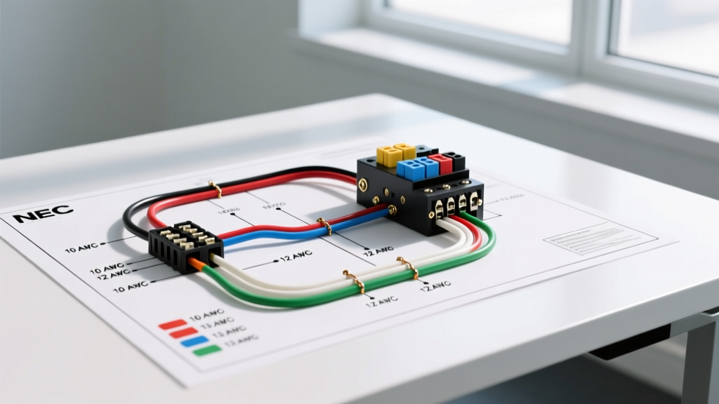
2026 NEC Wire Gauge & Breaker Sizing Matrix
One of the most critical steps in executing a heat pump electrical wiring diagram is sizing the overcurrent protection and conductors correctly. You must look at the unit's data plate for two specific values: MCA (Minimum Circuit Ampacity) and MOCP (Maximum Overcurrent Protection). The MCA dictates your wire size, while the MOCP dictates your breaker size.
| Unit Capacity (Tons) | Typical MCA (Amps) | MOCP (Breaker) | Min. Copper Wire Gauge (THHN) | Min. Conduit Size (LFMC) |
|---|---|---|---|---|
| 2.0 Ton (SEER2 16+) | 14.5 A | 20 A | 12 AWG | 1/2 inch |
| 3.0 Ton (SEER2 18+) | 21.2 A | 30 A | 10 AWG | 1/2 inch |
| 4.0 Ton (Variable Speed) | 28.0 A | 40 A | 8 AWG | 3/4 inch |
| 5.0 Ton (Variable Speed) | 34.5 A | 50 A | 8 AWG | 3/4 inch |
Note: In 2026, pricing for 8 AWG THHN copper averages around $1.65 per foot, while 10 AWG sits near $0.95 per foot. Always factor in 15% extra for conduit bends and panel termination.
Decoding the Reversing Valve (O vs. B Terminals)
The most common point of failure when reading a heat pump electrical wiring diagram is the reversing valve solenoid. This valve physically shifts the refrigerant flow, changing the system from cooling mode (where the indoor coil is the evaporator) to heating mode (where the indoor coil becomes the condenser).
The wiring diagram will show the solenoid connected to the 24V transformer and controlled by a relay on the defrost board or main control board. However, the logic varies strictly by manufacturer:
Energize in Cooling (O Terminal)
Brands like Trane, American Standard, Carrier, and Lennox typically use the O terminal. In this configuration, the reversing valve is de-energized by default (resting in heating mode). When the thermostat calls for cooling, it sends 24V to the O terminal, energizing the solenoid and shifting the valve to cooling. If you wire a Trane unit to a B-terminal logic board, the system will blow cold air when calling for heat, and hot air when calling for AC.
Energize in Heating (B Terminal)
Brands like Rheem, Ruud, and Goodman typically use the B terminal. Here, the valve rests in cooling mode. When the thermostat calls for heat, it sends 24V to the B terminal, energizing the solenoid to shift into heating mode. Most modern smart thermostats (like the Ecobee SmartThermostat Premium or Nest Learning Thermostat 4th Gen) feature an 'O/B' configuration menu in the software setup to accommodate both logic types without requiring physical wire swaps.
Defrost Board and Sensor Wiring Nuances
Unlike gas furnaces, heat pumps require a defrost cycle to melt ice accumulation on the outdoor coil during winter operation. The heat pump electrical wiring diagram will route the outdoor fan motor and the reversing valve through the defrost board.
When the defrost board initiates a cycle (usually based on a 50°F coil temperature and a 30-minute compressor run-time demand), it performs three actions simultaneously:
- Reverses the Valve: Shifts the unit into cooling mode to send hot discharge gas to the outdoor coil.
- Kills the Outdoor Fan: Stops the fan motor to allow the coil temperature to rise rapidly and melt the ice.
- Engages Auxiliary Heat: Sends a 24V signal to the indoor air handler's 'W2' or 'Aux' terminal to turn on the electric heat strips. This prevents the home from being blasted with cold air while the system is in defrost.
Modern 2026 units utilize advanced thermistors rather than mechanical capillary tube thermostats. These thermistors measure resistance (in ohms) which changes with temperature. The wiring diagram will specify the exact resistance curve (e.g., 10k ohms at 77°F). If you are troubleshooting a unit stuck in defrost, use your multimeter to measure the thermistor resistance; an open circuit (OL) indicates a severed sensor wire, while a short (0 ohms) indicates a failed sensor head.
Real-World Troubleshooting Edge Cases
Even with a perfect heat pump electrical wiring diagram, field conditions introduce variables that can trip up experienced professionals. Here are specific edge cases to watch for:
1. Dual-Fuel Configuration Jumpers
In dual-fuel systems (a heat pump paired with a gas furnace instead of an electric air handler), the wiring diagram changes significantly. The 'W2' terminal on the thermostat no longer controls electric strip heat; it controls the gas valve relay. You must physically remove the factory-installed jumper between 'W1' and 'W2' on the outdoor control board, or the system will attempt to run the heat pump compressor and the gas furnace simultaneously, causing severe high-head pressure faults.
2. ECM Blower Motor Programming
Variable-speed ECM (Electronically Commutated Motor) blowers require specific DIP switch or jumper settings to match the outdoor unit's tonnage. If the wiring diagram shows a 3-ton condenser connected to an air handler with a 5-ton ECM motor module, and the module is not programmed down to 3 tons via the board jumpers, the system will over-deliver airflow. This results in poor latent heat removal (high indoor humidity) in the summer and excessive noise.
3. The 'C' Wire Voltage Drop
Long thermostat wire runs (over 50 feet) using standard 18 AWG wire can suffer from voltage drop, causing the smart thermostat to reboot randomly or the contactor to chatter. The Air Conditioning Contractors of America (ACCA) recommends upsizing to 16 AWG thermostat wire for runs exceeding 75 feet to ensure a solid 24VAC signal reaches the outdoor contactor coil and reversing valve solenoid.
Summary
Mastering a heat pump electrical wiring diagram requires more than just connecting color-coded wires; it demands an understanding of thermodynamic logic, manufacturer-specific relay sequences, and strict adherence to the 2026 NEC safety codes. By verifying your MCA/MOCP ratings, correctly identifying the O/B reversing valve logic, and ensuring your low-voltage control circuits are free from voltage drop, you guarantee a safe, efficient, and long-lasting installation. Always keep the manufacturer's schematic taped inside the condenser access panel for future service technicians.