
Deconstructing the Wiring Diagram for Recessed Lights
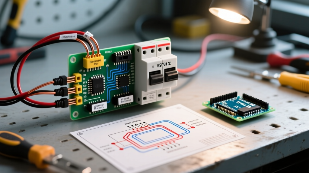
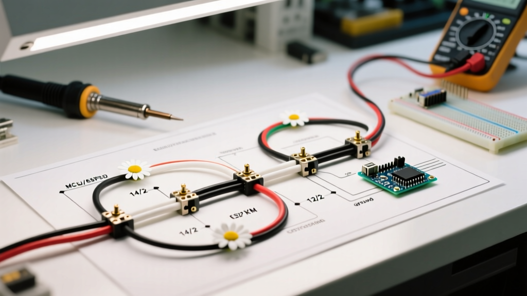
Installing recessed lighting (often referred to as can lights or downlights) requires a precise understanding of circuit topology, box fill limitations, and modern code requirements. Unlike simple single-fixture appliance wiring, a recessed lighting layout typically utilizes a daisy-chain configuration. This means the electrical current flows from the breaker panel to a wall switch, and then sequentially through multiple light housings. Understanding the correct wiring diagram for recessed lights is critical to preventing voltage drop, ensuring proper grounding, and avoiding thermal cutoff failures.
In modern residential and commercial construction, the shift toward integrated LED housings—such as the Halo H750RICAT or the ultra-thin Lithonia Lighting WF6 wafer lights—has changed the physical footprint of the junction box, but the fundamental electrical principles remain governed by the National Electrical Code (NEC). This tutorial breaks down the power-at-switch daisy-chain diagram, which is the industry standard for 2026 installations.
Power-at-Switch vs. Power-at-Light: The Modern Standard
Historically, electricians often used a "power-at-light" switch loop, where the hot and neutral from the panel entered the first ceiling fixture, and a single 2-wire cable dropped down to the switch. However, this method is now largely obsolete for new installations.
The NEC 404.2(C) Neutral Requirement
Modern smart dimmers and occupancy sensors (like the Lutron Caseta or Leviton Decora smart lines) require a dedicated neutral wire at the switch box to power their internal Wi-Fi or Zigbee radios. Therefore, the correct wiring diagram for recessed lights today mandates a power-at-switch topology. The 14/2 or 12/2 NM-B (Romex) cable from the panel enters the switch box first. From the switch box, a 3-wire cable (or two separate 2-wire cables depending on local amendments) carries the constant hot, the neutral, and the ground up to the first recessed light, while the switch leg interrupts the hot wire.
Material Specifications and Load Calculations
Before pulling wire, you must calculate the load and select the appropriate cable gauge. Most modern LED recessed lights draw between 9W and 14W each. Even on a 15-amp circuit (1,800W maximum continuous load), you could theoretically daisy-chain over 100 LED fixtures. However, voltage drop and physical box fill limitations dictate practical limits.
| Circuit Breaker | NM-B Cable Type | Max Continuous Load | Recommended Housing Type | Wire Connector Spec |
|---|---|---|---|---|
| 15 Amp | 14/2 NM-B (with ground) | 1,440 Watts | IC-Rated, Airtight (e.g., Halo H750RICAT) | Wago 221-413 (3-port) or Ideal 33 Tan |
| 20 Amp | 12/2 NM-B (with ground) | 1,920 Watts | IC-Rated, Airtight (e.g., Lithonia WF6) | Wago 221-413 (3-port) or Ideal 34 Yellow |
Box Fill Calculations (NEC Article 314.16)
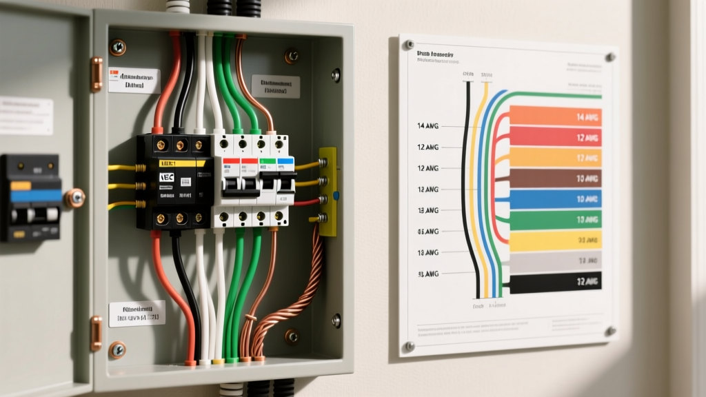
When daisy-chaining, the junction box inside the recessed housing must accommodate incoming power, outgoing power to the next light, and the fixture's internal whip. According to NEC Table 314.16(B), each 14 AWG conductor requires 2.0 cubic inches of space, and each 12 AWG requires 2.25 cubic inches. A standard 4x1.5 inch octagonal junction box provides 21 cubic inches. If your daisy-chain wiring diagram calls for multiple cables entering a single remodel housing, verify the housing's integrated junction box volume to avoid code violations and overheating.
Step-by-Step Execution: The Daisy-Chain Method
Follow this sequence to execute the wiring diagram safely and efficiently.
Step 1: Switch Box Preparation
- Turn off the breaker and verify zero voltage with a non-contact tester and a multimeter.
- Route the 14/2 NM-B cable from the panel to the single-gang switch box.
- Route a 14/3 NM-B cable (or a dedicated 14/2 switch leg, depending on your neutral routing strategy) from the switch box up to the first recessed light housing.
- Strip exactly 3/4 inch of insulation from the conductors. If using Wago 221 lever nuts, the strip length must be exactly 11mm (marked on the back of the connector).
Step 2: Inter-Can Connections (The Daisy Chain)
At each recessed housing junction box, you will connect three sets of wires: the incoming feed, the outgoing feed to the next light, and the fixture's internal pigtail.
- Neutrals (White): Connect the incoming white, outgoing white, and the fixture's white pigtail together. This maintains the neutral path for downstream lights and smart switches.
- Hots (Black): Connect the incoming switched-hot (returning from the wall switch), the outgoing black (feeding the next light), and the fixture's black pigtail.
- Grounds (Bare/Green): Connect all bare copper wires together, including a pigtail to the metal junction box if it is not self-grounding. Use a green wire nut or a Wago 221 with the green ground adapter.
Step 3: Securing and Strain Relief
Every NM-B cable entering the housing's junction box must be secured by an internal Romex clamp. Failure to engage the strain relief clamp can cause the wire's insulation to slice against the metal knockout edge over time, leading to a dead short and a tripped AFCI breaker.
Critical Edge Cases and Failure Modes
Even with a perfect wiring diagram for recessed lights, physical installation errors can cause system failures. Be aware of these specific edge cases:
The Thermal Cutoff Trip: Most IC-rated (Insulation Contact) housings, like the Halo H750RICAT, feature a bimetallic thermal protection switch. If insulation is packed too tightly over the housing's heat sink, or if a 65W incandescent bulb is installed in a fixture rated for 40W, the internal temperature will exceed 90°C (194°F). The switch will trip, cutting power to the daisy-chain. It will automatically reset once the temperature drops below 75°C (167°F), resulting in a frustrating cycle of lights turning off after 20 minutes and coming back on when cool.
Flickering on Dimmer Circuits
If your wiring diagram includes a dimmer switch, ensure the dimmer is specifically rated for LED loads (e.g., Lutron Diva LED+). Traditional TRIAC dimmers designed for incandescent loads will cause integrated LED drivers to flicker or buzz because they cannot handle the low-wattage capacitive load of modern wafer lights. Adjust the dimmer's low-end trim potentiometer to eliminate dropout.
NEC Code Compliance and Safety Mandates
Adhering to the NFPA National Electrical Code is non-negotiable for fire safety and insurance compliance. Specifically, Article 410 governs luminaires, mandating that recessed fixtures installed in insulated ceilings must be identified as IC-rated and equipped with thermal protection. Furthermore, all 15A and 20A residential lighting circuits must now be protected by AFCI (Arc-Fault Circuit Interrupter) breakers at the panel.
For energy efficiency and thermal management, selecting fixtures that meet Energy Star Luminaires specifications ensures the LED driver will not overheat the compact junction boxes typical of modern slim-profile recessed lights. Always verify that your chosen components carry a valid UL Electrical Safety certification mark, as uncertified imported fixtures often lack the necessary thermal cutoffs and use undersized internal wiring that poses a severe fire hazard.
Summary Checklist for the Electrician
- Verify power-at-switch topology to support future smart home upgrades.
- Calculate box fill volume before daisy-chaining more than two cables into a single remodel housing.
- Use IC-rated, airtight housings for any ceiling penetrating an insulated attic space.
- Strip wires to exact manufacturer specifications (11mm for Wago, 3/4 inch for standard wire nuts).
- Test the entire daisy-chain with an AFCI breaker before closing the ceiling drywall.
By strictly following this wiring diagram for recessed lights and respecting the physical limitations of modern LED housings, you will achieve a safe, code-compliant, and flicker-free lighting installation that will last for decades.