
The Critical Role of Transfer Switches in Mobile Power Systems
When engineering a 120/240V AC electrical system for a Class A motorhome, Sprinter camper van, or mobile command center, managing multiple AC sources is non-negotiable. An Automatic Transfer Switch (ATS) acts as the traffic cop for your rig's alternating current, safely isolating shore power from your onboard generator or high-capacity inverter-charger. Without a properly wired ATS, you risk catastrophic backfeeding, destroyed inverter MOSFETs, and severe shock hazards.
This comprehensive guide breaks down the exact wiring diagram for a transfer switch in a 50-amp RV application, specifically focusing on integrating a Go Power! GP-TS-50 (50-Amp ATS) with a modern lithium-backed inverter system and shore power pedestal. As of 2026, with the widespread adoption of 48V-to-120V split-phase inverter systems, understanding neutral-ground bonding and precise torque specifications is more critical than ever.
⚠️ NFPA 1192 & NEC Article 551 Compliance Warning:According to NFPA 1192 (Standard for Recreational Vehicles) and NEC Article 551, the neutral conductor and the grounding conductor must be bonded at the source of power (the shore pedestal or the generator), but never within the RV's internal distribution panel. Your ATS must maintain this isolation to prevent parallel neutral paths, which will instantly trip GFCI breakers at the campground pedestal and pose a lethal electrocution risk.
Core Components: Anatomy of a 50-Amp RV ATS
For this wiring diagram, we are utilizing the Go Power! GP-TS-50, a heavy-duty 50-amp automatic transfer switch widely used in high-end 2026 RV builds. Priced around $245, it features a built-in time-delay relay that prevents the inverter or generator from taking the load until the AC voltage stabilizes, protecting sensitive electronics from brownout damage.
Terminal Block Layout
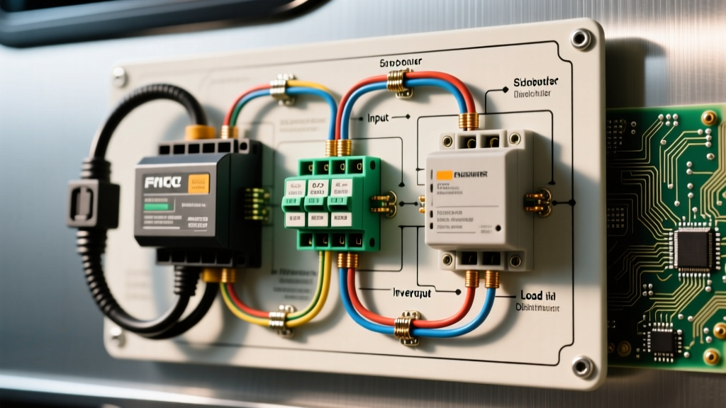
- Input 1 (SHORE): L1, L2, N, G (50A 120/240V Split-Phase from the campground pedestal)
- Input 2 (GEN/INV): L1, L2, N, G (50A 120/240V from the onboard generator or dual-leg inverter like the Victron Quattro)
- Output (MAIN): L1, L2, N, G (Feeds the RV's main AC breaker panel)
Step-by-Step Wiring Diagram Flow
Follow this exact sequence to route your 6 AWG THHN/THWN conductors. Always disconnect the negative terminal of your house battery bank before beginning any AC wiring.
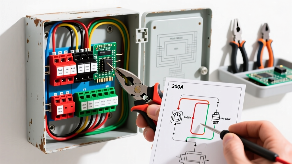
- Route Shore Power Input: Feed your 50A shore power cord (4-wire: Black, Red, White, Green) into the ATS enclosure via a 3/4-inch NPT strain relief fitting. Terminate Black to SHORE L1, Red to SHORE L2, White to SHORE N, and Green to SHORE G.
- Route Inverter/Generator Input: Feed the AC Out of your inverter-charger or onboard generator into the GEN/INV terminals. Crucial Edge Case: If using a Victron MultiPlus or Quattro, ensure the inverter's internal transfer switch is configured correctly so it doesn't 'fight' the external ATS. Ideally, bypass the inverter's internal AC-in relay if an external ATS is managing the generator.
- Route Main Panel Output: Wire the MAIN output terminals directly to the main lugs of your RV's AC distribution panel (e.g., a Progressive Dynamics PD4560CSV).
- Ground Bus Consolidation: All ground wires (Shore G, Gen G, Main G) terminate on the same continuous grounding bus bar inside the ATS. The ground is never switched; it is always bonded straight through.
- Apply Calibrated Torque: Using a calibrated torque screwdriver (such as the CDI 401SM), tighten all terminal block screws to exactly 35 in-lbs. Under-torqued 6 AWG wires will cause thermal arcing and melt the ATS housing under continuous 40A+ loads (like running dual rooftop A/C units).
Wire Gauge, Breaker Sizing, and Torque Matrix
Selecting the correct wire gauge and overcurrent protection is vital for passing RVIA inspections. Refer to the matrix below for 2026 standard mobile applications.
| Application | Wire Gauge (Copper) | Breaker Size | Terminal Torque |
|---|---|---|---|
| 50A Shore to ATS | 6 AWG THHN/THWN | 50A (2-Pole) | 35 in-lbs |
| 30A Shore to ATS | 10 AWG THHN/THWN | 30A (1-Pole) | 20 in-lbs |
| ATS to Main Panel (50A) | 6 AWG THHN/THWN | 50A (2-Pole Main) | 35 in-lbs |
| Grounding Bus Jumper | 6 AWG Bare/Green | N/A | 40 in-lbs |
The Neutral-Ground Bonding Dilemma
The most common failure point in DIY camper van and RV electrical builds is improper neutral-ground bonding. As detailed in the Victron Energy Wiring Unlimited Guide, mobile systems must dynamically manage where the neutral and ground are bonded.
How the ATS Handles the Bond
- Shore Power Mode: The neutral-ground bond exists at the campground pedestal. The ATS passes the neutral straight through to the main panel. The main panel's neutral bus and ground bus must remain isolated (separated).
- Generator Mode: Most onboard RV generators (like the Cummins Onan RV QD 10000) have an internal neutral-ground bond. The ATS switches both the Line and Neutral conductors, ensuring the shore power's neutral (and its distant bond) is completely disconnected from the RV's internal wiring.
- Inverter Mode: If using a standalone inverter, you must install a neutral-ground bonding relay that activates only when the inverter is powering the AC panel. High-end inverter-chargers (like the Victron Quattro) have this relay built-in, but it must be wired to the ATS's dry contact or triggered via the system's BMS.
Troubleshooting Edge Cases & Failure Modes
Even with a perfect wiring diagram for a transfer switch, real-world conditions introduce variables. Here is how to diagnose common ATS anomalies:
| Symptom | Root Cause | Diagnostic Fix |
|---|---|---|
| GFCI trips at shore pedestal immediately upon plugging in. | Duplicate Neutral-Ground bond inside the RV main panel or inverter. | Verify the RV main panel neutral bus is completely isolated from the ground bus. Remove any green bonding screw in the sub-panel. |
| ATS hums loudly but fails to transfer to shore power. | Low shore voltage (brownout) preventing the solenoid coil from fully engaging. | Measure pedestal voltage. If below 104V, the ATS time-delay relay will lock out to protect the A/C compressor. Use an EMS (Electrical Management System). |
| Inverter throws 'AC Input Phase Error' or rejects generator. | L1 and L2 are swapped or out of phase between the generator and the ATS. | Use a multimeter to verify 240V across L1 and L2 at the GEN input terminals. If reading 0V, phases are crossed or generator is single-leg only. |
| Melted plastic housing near SHORE L1 terminal. | Thermal arcing due to loose 6 AWG stranded wire under the terminal clamp. | Cut back damaged wire, apply new ferrule or re-tin, and torque to exactly 35 in-lbs. Install thermal camera monitoring for first 24 hours. |
Manual vs. Automatic: Cost & Efficiency in 2026
While the wiring diagram for an automatic transfer switch dominates the RV market, manual transfer switches (like the Reliance Controls 31406CRK, ~$140) are still used in budget food trucks and off-grid trailers. A manual switch requires the user to physically flip a lever, guaranteeing zero overlap between sources. However, in a modern 2026 camper van build featuring a 48V lithium architecture and automated climate control, an ATS is mandatory. The ATS allows the system's BMS to auto-start the generator when the battery bank drops below 20% State of Charge (SoC), seamlessly transferring the AC load without waking the occupants.
Final Inspection Checklist
Before energizing the system, perform a continuity test between the RV's chassis ground and the neutral bus in the main panel with all power sources disconnected. You should read OL (Open Loop). If you read continuity, you have an illegal and dangerous neutral-ground bond inside the vehicle that must be severed before connecting to shore power.
By strictly adhering to this wiring diagram for a transfer switch, respecting torque specifications, and understanding the physics of neutral-ground bonding, you ensure your mobile electrical system is safe, efficient, and fully compliant with national and mobile electrical codes.