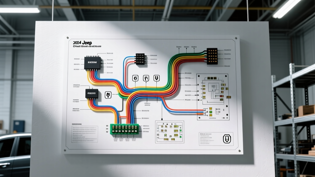

Understanding the WJ Multiplex Architecture
The 2004 Jeep Grand Cherokee represents the final production year of the highly regarded WJ generation. While celebrated for its solid axle durability and quadra-drive capabilities, its electrical system is notoriously complex. Unlike older vehicles that relied on simple point-to-point analog wiring, the 2004 WJ utilizes a multiplexed network centered around the PCI (Programmable Communications Interface) bus. When you are planning aftermarket installations—whether integrating auxiliary off-road lighting, winch solenoids, or dual-battery isolators—relying on a generic schematic will lead to catastrophic module failures. You must use the exact wiring diagram for 2004 Jeep Grand Cherokee models to trace circuits accurately and avoid overloading the Body Control Module (BCM).
Planning an installation without consulting the factory diagram often results in tapping into data lines instead of power feeds, which instantly fries the BCM or the Powertrain Control Module (PCM). This guide breaks down the architectural nodes, wire color standards, and specific installation planning steps required for the 2004 WJ platform.
Primary Electrical Distribution Nodes
Before cutting into any harness, you must understand where the vehicle distributes power and data. The 2004 Grand Cherokee splits its electrical management across three primary physical locations.
| Node Name | Physical Location | Primary Function | Diagram Section Reference |
|---|---|---|---|
| PDC (Power Distribution Center) | Engine bay, driver side fender | High-current fuses, main relays, battery feed distribution | Power Distribution (PG-70) |
| Junction Block (JB) | Interior, left kick panel | Low-current cabin fuses, flashers, BCM integration | Instrument Panel (PG-80) |
| BCM (Body Control Module) | Underneath the right rear passenger seat | Multiplexing, lighting logic, theft deterrence, PCI bus gateway | Module Communications (PG-110) |
CRITICAL WARNING: Never tap directly into a BCM output wire to trigger a high-draw accessory relay. The BCM uses low-amperage solid-state drivers (often maxing out at 2A to 5A). Always use the wiring diagram to locate a PDC relay coil trigger or use an isolated automotive relay to buffer the BCM signal.
Decoding the Wiring Diagram: Wire Colors and SAE Standards
Chrysler's wiring diagram for the 2004 Jeep Grand Cherokee follows strict color-coding conventions. Understanding these colors saves hours of diagnostic time with a multimeter.
- Pink or Red: Unswitched battery hot (B+). Usually 10 AWG to 12 AWG for main feeds.
- Black: Chassis ground. Ranging from 14 AWG for accessories to 4 AWG for engine block grounds.
- Dark Green (with tracer): Fused ignition switch output (run/start).
- Violet/White: PCI Bus data line. Never tap this wire for power.
- Yellow: Fused battery feed, typically switched via a relay for high-draw cabin accessories.
Wire Gauge Selection for Aftermarket Mods
When planning your install, wire gauge selection must account for both the amperage draw and the physical length of the wire run to prevent voltage drop. According to MAD Enterprises' automotive wire sizing standards, a 15-foot run drawing 20 amps requires a minimum of 12 AWG wire to maintain a safe voltage drop below 3%. For high-draw accessories like a 12,000 lb winch, you must upgrade to 1/0 AWG or 2/0 AWG welding cable to handle the 400+ amp transient spikes without melting the insulation.
Step-by-Step Installation Planning: Auxiliary Off-Road Lighting
Let us apply the wiring diagram for the 2004 Jeep Grand Cherokee to a common installation: adding four 55W Hella halogen auxiliary driving lights. Total draw is 220W. At a resting alternator voltage of 13.8V, the draw is approximately 16 amps.
- Source the Trigger: Do not splice the headlight switch harness. Consult the PDC section of the diagram. Locate the Fog Lamp Relay (usually labeled K7). Tap into the relay's output wire (often Dark Green/Orange) using a Posi-Tap connector. This ensures your aux lights only turn on when the fog lights are active, complying with DOT regulations.
- Install the Main Relay: Mount a heavy-duty 30A Bosch-style 5-pin relay in the engine bay.
- Terminal 30: Connect directly to the PDC battery stud using 10 AWG wire and an inline 20A MAXI fuse.
- Terminal 87: Run 12 AWG wire to the auxiliary lights.
- Terminal 86: Connect to the fog lamp trigger wire tapped in Step 1.
- Terminal 85: Ground to the radiator support (ensure bare metal contact).
- Grounding the Lights: The WJ chassis relies heavily on the left kick panel ground splice (G200). However, for exterior lighting, always run dedicated ground wires back to the negative battery terminal or a verified engine-to-chassis ground strap to prevent back-feeding through the PCI bus.
Advanced Planning: Dual-Battery Isolator Integration
Overlanding builds frequently require a secondary deep-cycle battery. When planning a dual-battery setup in the 2004 Grand Cherokee, space in the engine bay is severely limited by the 4.7L V8 or 4.0L I6 engine covers. You will likely need to mount the secondary battery in the rear cargo area using a custom fabricated steel tray.
Use an intelligent isolator like the Hellroaring DCC500B or a National Luna unit. The wiring diagram dictates that you must run 1/0 AWG positive and negative cables from the front PDC and engine block ground, respectively, through the factory firewall grommet (located behind the brake booster). Do not use the smaller interior firewall grommets, as the 1/0 AWG cable will tear the rubber seal, leading to water intrusion and interior mold.
Known WJ Failure Modes That Mimic Wiring Faults
Before tearing apart your dashboard based on a wiring diagram, rule out these three notorious 2004 WJ failure modes that mimic complex electrical shorts:
1. Ignition Switch Connector Melt
The WJ ignition switch is located on the steering column and actuated by a metal rod. The 10-pin connector (Mopar part #56041018AB) is notorious for overheating and melting due to high resistance. If your wiring diagram shows power leaving the ignition switch but your accessory circuits are dead, inspect this physical connector for brown scorch marks before tracing the harness.
2. G200 Ground Splice Failure
Located behind the left kick panel, the G200 ground splice connects multiple BCM and instrument cluster grounds. If it corrodes, you will experience gauge cluster flickering, erratic fuel gauge readings, and phantom PCI bus codes. A simple voltage drop test across the ground strap will confirm this failure.
3. Alternator Field Control Issues
Unlike older vehicles with internal voltage regulators, the 2004 Grand Cherokee's PCM controls the alternator field via a two-wire circuit (Dark Green and Dark Green/Light Blue). If your battery is overcharging or undercharging, do not just replace the alternator. Use a digital multimeter to verify the PWM signal from the PCM.
Essential Diagnostic Tools for 2026
Working on multiplexed Chrysler vehicles requires modern diagnostic equipment. Relying on a basic test light can damage the PCM. Ensure your toolkit includes:
- Fluke 87V Industrial Multimeter: Essential for measuring voltage drop and verifying PCI bus square-wave signals. For deeper insights on testing automotive networks, refer to the Fluke automotive electrical testing guides.
- Power Probe IV: Allows you to inject power and ground safely while monitoring circuit resistance, drastically speeding up relay and solenoid testing.
- Posi-Tap and Posi-Lock Connectors: Abandon 3M Scotchloks and T-taps. They fray stranded automotive wire and invite corrosion. Posi-products provide a vibration-proof, waterproof connection.
Sourcing Factory Diagrams and Connectors
To access the complete, high-resolution wiring diagram for the 2004 Jeep Grand Cherokee, you will need a subscription to a service like Mitchell1 DIY or ALLDATA. Alternatively, purchasing the original 2004 Chrysler Factory Service Manual (FSM) on CD or PDF provides the most accurate pinout charts for the PCM and BCM. For replacement pigtails and weather-pack connectors, NHTSA vehicle databases can help you identify specific recall-related wiring harness revisions, while Mopar's official parts catalog ensures you get OEM-grade terminals that resist vibration-induced fretting corrosion.
By respecting the multiplexed architecture and strictly following the factory wiring diagram, your 2004 Jeep Grand Cherokee will remain reliable on the trail and the highway, free from the electrical gremlins that plague poorly planned aftermarket installations.