
Why a Manual Transfer Switch is Non-Negotiable
When the grid fails, the temptation to backfeed a home through a dryer outlet using a 'suicide cord' is a fatal hazard that endangers utility lineworkers and homeowners alike. According to OSHA's portable generator guidelines, improper backfeeding is a leading cause of electrocution during storm recovery. The only code-compliant, safe method for integrating a portable generator into a home's electrical system is utilizing a proper wiring diagram for manual transfer switch (MTS) integration. This guide breaks down the exact topology, component selection, and edge-case troubleshooting required for a 30-amp, 6-circuit interior MTS setup as of 2026.
Core Components & 2026 Pricing Matrix
Before pulling wire, you must procure compatible hardware. A 30-amp system is the standard for portable generators in the 7,500W to 9,000W running watt class. Below is the recommended bill of materials based on current 2026 market pricing:
| Component | Recommended Model | Function | Avg. Cost (2026) |
|---|---|---|---|
| Manual Transfer Switch | Generac 6294 (6-Circuit, 30A) | Isolates utility from generator; routes power to 6 critical branch circuits. | $340 - $380 |
| Power Inlet Box | Reliance Controls PB30 | Exterior NEMA L14-30R receptacle for generator connection. | $55 - $70 |
| Main Panel Breaker | Siemens Q230 (30A Double-Pole) | Protects the feeder cable running from the main panel to the MTS. | $15 - $22 |
| Generator Cord | 30-Amp 10/4 SOOW (L14-30P to L14-30R) | Connects generator to the exterior inlet box. | $80 - $120 |
The Wiring Diagram: Conceptual Power Flow
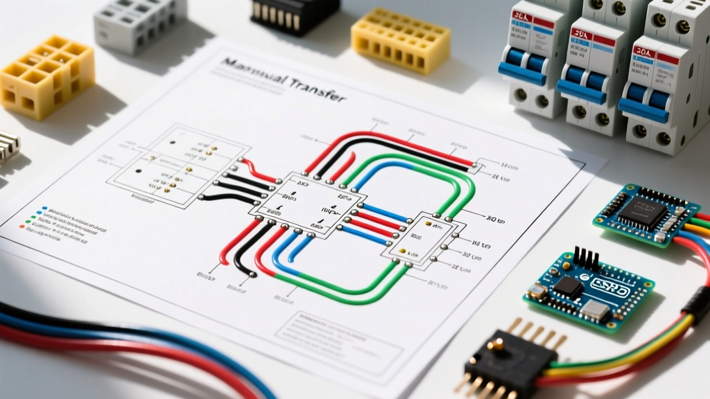
Understanding the wiring diagram for manual transfer switch setups requires visualizing three distinct power paths:
- Utility to Main Panel: Standard grid power enters the main service disconnect and feeds all branch circuits normally.
- Main Panel to MTS (Feeder): A dedicated 30A double-pole breaker in the main panel feeds a 10/4 feeder cable to the MTS. This provides utility power to the 6 selected critical circuits inside the MTS.
- Generator to MTS (Inlet): The generator plugs into the exterior inlet box, which routes a second 10/4 cable into the MTS. When the MTS toggles to 'GEN', the utility feeder is physically disconnected (break-before-make), and the generator inlet powers the 6 critical circuits.
CRITICAL SAFETY NOTE: The physical break-before-make mechanism inside the MTS ensures that generator power can never backfeed into the utility grid, protecting lineworkers repairing downed lines.
Wire Gauge & Conduit Sizing Matrix
Selecting the correct wire gauge is dictated by NEC Article 310 and the distance between your main panel and the MTS. Voltage drop becomes a significant factor in 240V circuits exceeding 50 feet.
| Run Length (One-Way) | Wire Gauge (Copper THHN/THWN-2) | Conduit Size (EMT or PVC) | Max Voltage Drop (240V) |
|---|---|---|---|
| Under 50 feet | 10 AWG | 1/2 inch (3/4 inch preferred for pulling) | < 1.5% |
| 50 to 100 feet | 8 AWG | 3/4 inch | < 2.5% |
| 100 to 150 feet | 6 AWG | 1 inch | < 3.0% |
Expert Tip: While 10 AWG is rated for 30 amps, running four 10 AWG THHN wires in a 1/2-inch EMT conduit pushes the NEC Chapter 9 Table 1 conduit fill limit (40% for 3+ wires). Always upsizing to 3/4-inch EMT reduces friction and prevents insulation scoring during the pull.
Step-by-Step Wiring Procedure
Step 1: Mount the Power Inlet Box
Install the Reliance PB30 inlet box on the exterior of the home, ideally within 10 feet of where the interior MTS will be mounted. Use 1/2-inch liquid-tight flexible metallic conduit (LFMC) to transition through the exterior wall into the interior cavity. Ensure the box is mounted at least 18 inches above grade to prevent snow or floodwater ingress.
Step 2: Run the Feeder and Inlet Cables
Run two separate 10/4 cable sets (or 4 individual THHN wires per set in conduit).
- Cable A (Feeder): From the main panel's new 30A breaker to the MTS utility input terminals.
- Cable B (Inlet): From the exterior inlet box to the MTS generator input terminals.
Step 3: Splice the Branch Circuit Pigtails
The Generac 6294 features six pre-wired 15A/20A pigtails (black for hot, white for neutral). Turn off the main utility breaker. Identify the six critical circuits in your main panel (e.g., refrigerator, furnace, sump pump, kitchen receptacles, well pump, and lighting). Disconnect the hot and neutral wires from these specific breakers in the main panel, and splice them to the corresponding MTS pigtails using purple or gray Wago 221 lever nuts. Do not use standard wire nuts in high-vibration or high-heat environments; lever nuts provide verifiable, gas-tight connections.
Step 4: Bond Grounds and Finalize Terminations
Connect the bare copper ground wires from both the feeder and inlet cables to the main panel's equipment grounding bar. Do not bond the neutral to the ground inside the MTS or the inlet box. The neutral-to-ground bond must only exist at the main service disconnect.
Critical Edge Case: Neutral Bonding & Ground Loops
The most common failure mode and code violation in DIY MTS installations involves neutral bonding. Most 6-circuit indoor transfer switches are 2-pole switches. They switch the two hot legs (L1 and L2) but leave the neutral continuously bonded through the system. If you use a portable generator that has a bonded neutral (where the generator's neutral is internally tied to its metal frame/ground), you create a parallel path for neutral current to flow back to the main panel through the equipment grounding conductors. This violates NEC 250.6 and can cause GFCI breakers on the generator to trip instantly, or worse, energize the generator's frame.
The Solution: You must use a 'floating neutral' generator for a 2-pole MTS. If your generator has a bonded neutral, you must locate the neutral bonding screw or jumper strap inside the generator's alternator terminal box and remove it, effectively converting it to a floating neutral system. Always verify with a multimeter that there is no continuity between the L14-30 plug's neutral blade and the ground blade before connecting to the inlet box.
NEC Compliance & AFCI/GFCI Considerations
As jurisdictions continue to adopt and enforce the 2023 NEC throughout 2026, inspectors are heavily scrutinizing generator-backed circuits. NEC Article 702 governs Optional Standby Systems. Because a 2-pole MTS does not switch the neutral, the branch circuits retain their connection to the main panel's neutral bar. If your home utilizes Combination AFCI (CAFCI) or Dual Function (DF) breakers for bedrooms and kitchens, these breakers may nuisance-trip when powered by the generator due to the generator's inherent harmonic distortion and slight frequency deviations. If this occurs, the code-compliant workaround is to install a standard thermal-magnetic breaker in the MTS for those specific circuits, provided the MTS itself offers the required branch-circuit overcurrent protection, or to upgrade to a 3-pole service-rated transfer switch that completely isolates the neutral.
For comprehensive code references, always consult the NFPA 70 National Electrical Code and review local amendments before pulling a permit.
Frequently Asked Questions
Can I wire a manual transfer switch to a subpanel instead of the main panel?
Yes, this is often an easier installation. You can feed a dedicated emergency subpanel directly from the MTS. The main panel feeds the MTS, and the MTS outputs to the subpanel. This eliminates the need to splice individual branch circuit pigtails inside the crowded main panel.
Do I need a permit to install a 30A manual transfer switch?
Absolutely. Per FEMA and Ready.gov safety guidelines, as well as local building codes, any permanent alteration to a home's electrical distribution requires an electrical permit and a final inspection to ensure the isolation of utility and generator power is mechanically sound.
What happens if I forget to turn off the main breaker when using the generator?
If you are using a properly wired MTS, nothing dangerous happens. The MTS physically prevents the generator power and utility power from mixing. However, leaving the main breaker on means that when utility power is restored, it will backfeed into the MTS utility input, and the system will sit idle until you manually flip the MTS switches back to the 'LINE' position.