
Mastering the Blueprint: Troubleshooting With a Basic Automotive Electrical Wiring Diagram
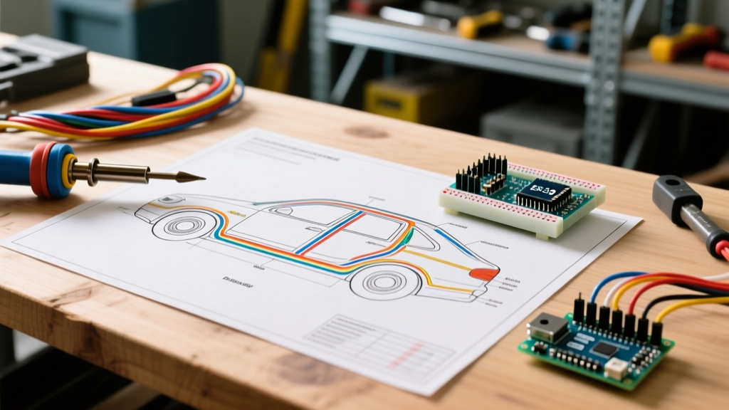
In the landscape of 2026 vehicle diagnostics, even a seemingly simple 12V circuit is intertwined with complex module logic. While advanced multiplex networks like CAN-FD and LIN bus dominate modern architecture, the foundation of all electrical diagnostics remains the basic automotive electrical wiring diagram. Whether you are tracking down a parasitic battery drain on a late-model SUV or diagnosing a failed blower motor resistor on a work truck, the schematic is your only reliable map. Relying on guesswork or blindly poking wires with a test light not only wastes time but risks frying sensitive Body Control Modules (BCMs). This guide breaks down exactly how to read, interpret, and troubleshoot using automotive wiring schematics with professional-grade precision.
Decoding the Legend: Symbols, Colors, and Node Identifiers
Before tracing a single wire, you must understand the schematic's language. While OEM diagrams (Ford, GM, Toyota, Honda) have slight stylistic variations, they all adhere to core international standards like ISO 6722 for wire coloring and DIN 72552 for terminal designations. According to the SAE International standards hub, standardized low-tension cable identification is critical for cross-manufacturer diagnostic consistency.
| Symbol / Code | Meaning | Troubleshooting Relevance |
|---|---|---|
| B+ / 30 | Constant Battery Positive | Hot at all times. If dead here, check main fusible links near the battery. |
| IG / 15 | Ignition Switched Power | Only hot in 'Run' or 'Start'. Used to trigger relays and wake up modules. |
| GND / 31 | Chassis Ground | The return path. 80% of electrical faults are poor grounds, not bad power feeds. |
| S142 | Splice Node (Example) | Indicates where wires join inside the harness. Crucial for finding hidden corrosion. |
| G201 | Ground Node (Example) | Physical bolt location to the chassis. Must be checked for paint, rust, or looseness. |
Wire Color Tracers
On a basic automotive electrical wiring diagram, wire colors are usually abbreviated (e.g., BLK/WHT for Black with a White stripe). Always verify the physical wire against the diagram, but remember that UV exposure and underhood heat can fade colors over time. Use the circuit number printed on the wire insulation as your secondary confirmation.
The 4-Step Diagnostic Workflow Using Wiring Diagrams
Professional technicians do not just 'look' at a diagram; they interrogate it. Follow this sequential workflow to isolate faults without unnecessary teardowns.
Step 1: Identify the Power Source and Ground Nodes
Locate the specific fuse and ground node for the failing circuit. If the diagram shows the circuit originating at Fuse 24 (15A) in the Underhood Bussed Electrical Center (UBEC) and grounding at G104 (left kick panel), your first step is to verify battery voltage at both sides of Fuse 24 with the key off. Next, locate G104 on the chassis and verify it is clean, tight, and free of dielectric grease or rust.
Step 2: Trace the Path Through Control Modules and Relays
Modern circuits rarely run directly from a switch to a load. A basic automotive electrical wiring diagram will show the switch sending a low-current logic signal to a module (like a BCM), which then grounds the coil side of a relay. The relay's switch side then sends high-current B+ to the load. Diagnostic Tip: If the load is dead, listen for the relay click. If it clicks, the control side (switch and module) is working; your fault is on the load side (power feed, wiring, or the component itself).
Step 3: Perform Voltage Drop Testing (Not Just Continuity)
Never use an ohmmeter to test a live circuit, and never rely solely on a continuity beep to verify a wire's health. A wire with only one strand of copper intact will beep for continuity but will fail under load. Instead, perform a dynamic voltage drop test. According to the Fluke Automotive Diagnostic Guide, a healthy wire or connection should drop no more than 0.1V under load. A drop of 0.5V or higher indicates high resistance, meaning the wire is corroded or the connector terminals are spread.
Step 4: Isolate the Component vs. the Harness
Once you have confirmed good B+ and a clean ground directly at the component's connector, the harness is cleared. If the component still fails to operate, the component itself is internally faulted. Always back-probe connectors using proper T-pin or back-probe tools; never pierce wire insulation with a test probe, as this introduces moisture and guarantees future corrosion.
Real-World Case Study: The Phantom Parasitic Draw
Vehicle: 2025 Mid-Size Crossover (CAN-Bus Architecture)
Complaint: Dead battery every 3 days.
Diagram Analysis: A basic automotive electrical wiring diagram for the interior lighting and door latch circuits revealed that the BCM monitors the door ajar switches to determine sleep states.
The Diagnosis: Using a DC amp clamp, we measured a parasitic draw of 210mA after the vehicle was locked. Modern vehicles require the CAN bus to 'sleep' (dropping draw below 40mA), which can take up to 30 minutes. The diagram showed that the driver's door latch microswitch provides a ground signal to BCM Pin 42. Even with the door closed, a scan tool showed 'Driver Door Ajar: Active'. The physical switch inside the latch assembly was sticking. The BCM never entered sleep mode, keeping the network awake and draining the battery. Replacing the $85 door latch assembly resolved the 210mA draw.
Diagnostic Decision Matrix: Symptom to Schematic
Use this matrix to quickly determine which section of the basic automotive electrical wiring diagram to focus on based on your initial symptoms.
| Observed Symptom | Diagram Section to Analyze | Primary Test to Perform |
|---|---|---|
| Component works intermittently or only when wiggling wires | Connectors, Splice Nodes (S-xxx), and Flex Zones (doors/hood) | Wiggle test with live voltage drop monitoring. |
| Fuse blows immediately upon activation | Load side of the relay, downstream harness routing near sharp metal | Short-finder tool or isolate branches at splice nodes. |
| Component works, but runs slowly or dimly | Both B+ feed and Ground (G-xxx) return paths | Voltage drop test on power and ground under load. |
| Unrelated components activate when one switch is pressed | Shared Ground Nodes (G-xxx) | Check for 'floating ground' causing back-feeding through other modules. |
2026 Tooling Requirements for Diagram-Based Troubleshooting
To effectively execute the tests derived from your wiring diagrams, you need the right equipment. The era of the $10 incandescent test light is over; using one on a modern CAN bus line can short the network and brick a $1,500 module.
- Digital Multimeter (DMM): The Fluke 87V (approx. $475) remains the industry standard for its high impedance (10 Megohms), which prevents loading down sensitive logic circuits, and its min/max recording for catching intermittent voltage drops.
- Circuit Load Tester: The Power Probe IV (approx. $260) allows you to inject power or ground directly into a component while referencing the wiring diagram, bypassing the vehicle's harness to quickly verify component health.
- Breakout Boxes & T-Pins: Essential for back-probing module connectors without damaging the delicate gold-plated terminals. Never use paperclips or sewing needles.
- Thermal Imaging Camera: Tools like the FLIR ONE Edge (approx. $400) can visually pinpoint high-resistance connections shown on your diagram by detecting the heat generated by voltage drop.
Common Mistakes When Reading Automotive Schematics
Even seasoned DIYers make critical errors when interpreting a basic automotive electrical wiring diagram. Avoid these pitfalls:
- Ignoring the 'Current Flow' vs 'Topographical' layout: Some diagrams show circuits logically from top to bottom (power to ground), while others show them topographically (how they are physically routed). Know which style your OEM uses.
- Assuming Internal Module Wiring is Visible: A diagram will show pins going into a BCM, but the internal logic gates and transistors are represented as a simple black box. Do not try to diagnose inside the box; test the inputs and outputs.
- Overlooking Shielding and Drain Wires: In 2026, many sensor circuits (like crankshaft position or wheel speed) use shielded twisted pairs. The diagram will show a drain wire connected to a specific 'clean' or 'signal' ground, not the main chassis ground. Grounding a shield to the wrong node will introduce alternator whine or EMI faults.
Frequently Asked Questions
Where can I find accurate wiring diagrams for my specific vehicle?
Factory Service Manuals (FSM) are the gold standard. While OEM dealerships charge for access, subscriptions to professional databases like ALLDATA DIY, Mitchell1, or Identifix provide OEM-accurate basic automotive electrical wiring diagrams for most vehicles. Avoid free forum diagrams, as they are often mislabeled or from different trim levels.
What does a dotted line mean on an automotive wiring diagram?
A dotted or dashed line typically indicates a mechanical linkage, a shielded wire casing, or a component boundary (showing that two separate electrical terminals are housed within the same physical plastic casing or relay block).
How do I test a ground circuit shown on the diagram without tearing apart the interior?
Locate the ground node identifier (e.g., G302) on the diagram, then find its physical location using the vehicle's ground location index chart (usually found in the FSM). If accessing it requires dropping the headliner, you can perform a voltage drop test from the component's ground pin to the battery negative terminal while the circuit is active. A reading over 0.1V confirms the ground is faulty, saving you the teardown if the ground is actually fine.
Final Thoughts
Troubleshooting modern vehicles requires a methodical, evidence-based approach. The basic automotive electrical wiring diagram is not just a reference; it is your diagnostic contract with the vehicle. By mastering symbol identification, enforcing strict voltage drop testing protocols, and understanding module sleep logic, you can diagnose complex electrical faults faster and more accurately than technicians who rely on guesswork. Always consult authoritative resources, such as the NHTSA Vehicle Safety guidelines, when working near safety-critical systems like airbags (SRS) or high-voltage EV architectures, and always disconnect the 12V battery before performing invasive harness repairs.