
Translating Panel & Breaker Logic to Pit Bike Electricals
When most riders unbox a new import pit bike—such as an SSR 125, Thumpstar, or Apollo RFZ—they are greeted by a chaotic 'spaghetti' wiring harness. Unlike residential or industrial electrical systems that rely on centralized breaker panels to isolate faults, factory pit bike wiring often routes raw stator power directly to components with minimal inline glass fuses. This lack of a centralized 'panel' is the leading cause of melted stators, fried CDIs, and electrical fires in off-road motorcycles.
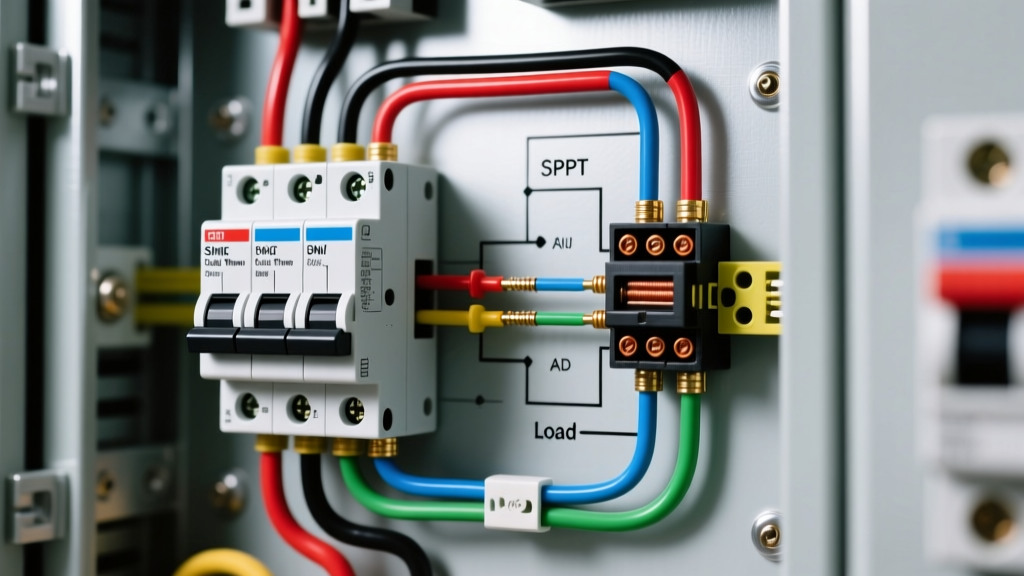
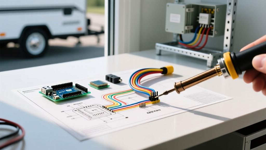
Applying a Panel & Breaker Guide methodology to a 12V DC micro-system means treating your pit bike's electrical architecture with the same respect as a household sub-panel. In this comprehensive guide, we will decode the ultimate wiring diagram for pit bike power distribution, focusing on centralized fusing, main kill switch interrupt circuits, and protecting your critical ignition components from catastrophic short circuits.
The Core Anatomy of a Pit Bike DC Micro-Panel
Before tracing the wires, you must understand the flow of current. A pit bike does not have an alternator like a car; it uses a magneto stator. The stator generates raw, unregulated AC voltage. The 'breaker' logic in a pit bike begins immediately after the AC is converted to DC.
- The Source (Stator): Generates 60W to 120W of raw AC power depending on the engine size (typically 50cc to 150cc clones).
- The Converter (Regulator/Rectifier): Converts AC to 12V DC and clips voltage spikes to a safe 14.4V threshold.
- The Main Breaker (Primary Fuse): A single high-amperage fuse (usually 10A to 15A) that acts as the main disconnect between the rectifier and the bike's wiring harness.
- The Panel (Fuse Block): A centralized distribution block that routes protected 12V power to the lighting, horn, and DC-CDI (if equipped).
Decoding the Wiring Diagram for Pit Bike Power Distribution
To properly wire a pit bike, we divide the schematic into three distinct zones: the high-voltage AC zone, the DC distribution panel, and the ignition interrupt (kill) circuit.
Zone 1: Stator to Rectifier (The Unprotected AC Zone)
The wires exiting the left-side engine casing (usually yellow and pink/white) carry raw AC voltage. Do not place standard DC automotive fuses in this AC circuit. The heat and vibration of the engine bay will degrade standard blade fuses, and the AC waveform can cause improper arcing inside a DC-rated fuse housing. According to SAE Standard J1128, wiring in this high-heat zone must utilize cross-linked polyethylene (XLPE) insulation rated for 125°C to prevent the insulation from melting against the engine block.
Zone 2: The Main Fuse and Distribution Panel
Once the rectifier converts the power to 12V DC, it must pass through a main fuse. In a proper panel setup, this 15A main fuse acts as your 'Main Breaker.' From here, the positive 12V feed travels to a centralized fuse block. As of 2026, the industry standard for DIY pit bike builders is adapting marine-grade fuse blocks, which feature tin-plated copper buses that resist the extreme moisture and mud inherent to off-road riding.
Zone 3: The Kill Switch as a Control Breaker
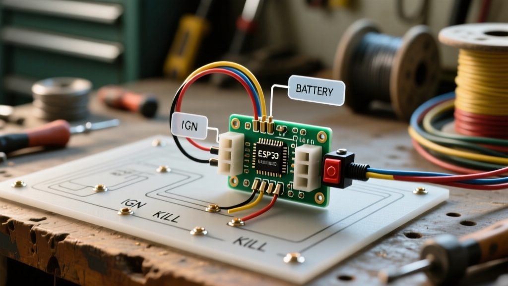
The kill switch on a pit bike does not 'break' the main 12V power like a household light switch. Instead, it acts as a logic interrupt for the Capacitor Discharge Ignition (CDI). Understanding your CDI type is critical for your wiring diagram:
- AC CDI (Most Common on SSR/Thumpstar): Powered directly by a dedicated stator coil (usually a black/red wire). The kill switch works by grounding this wire to the frame, shorting the ignition pulse to kill the engine.
- DC CDI (Common on Upgraded/Big Bore Bikes): Powered by the 12V DC battery/rectifier circuit. The kill switch works by interrupting the 12V positive feed (acting as a true series breaker).
Wire Gauge & Fuse Sizing Matrix for Pit Bikes
Using the correct wire gauge is non-negotiable. Chinese factory harnesses often use undersized 20 AWG wire for main feeds, leading to voltage drop and melted connectors. Use the following matrix when building your custom harness and panel.
| Circuit Function | Recommended Wire Gauge (SAE) | Max Fuse Rating | Typical Load / Notes |
|---|---|---|---|
| Rectifier to Main Panel | 12 AWG | 15A (Main) | Carries total system DC load |
| Headlight (AC or DC) | 14 AWG | 10A | 35W Halogen or 15W LED |
| Taillight / Brake Light | 16 AWG | 5A | LED upgrades draw < 1A |
| DC-CDI Power Feed | 16 AWG | 3A | Extremely sensitive to voltage drop |
| Horn / Accessories | 18 AWG | 5A | Use relay for high-draw horns |
| Kill Switch Ground Interrupt | 16 AWG | None (Unfused) | Must have zero-resistance path to frame |
Upgrading to a Marine-Grade Fuse Panel
Factory pit bikes use cheap inline glass fuse holders that corrode within a single muddy season. To establish a reliable 'breaker panel' on your bike, mount a Blue Sea Systems ST Blade Compact Fuse Block. Retailing for approximately $32 in 2026, this 6-circuit block features a negative bus bar and independent fuse covers.
Pro-Tip for Panel Mounting: Never mount the fuse block directly to the engine or airbox where high-pressure washes can force water into the terminals. Mount it under the seat cowl or behind the front number plate, and apply a thin layer of dielectric grease (like CRC Industries Marine Grease) to every spade terminal before inserting the ATO fuses.
Common Failure Modes & Troubleshooting
Even with a perfect wiring diagram, pit bikes suffer from specific electrical edge cases. Here is how to troubleshoot them using panel-logic diagnostics.
1. The Phantom Battery Drain
If you install a 12V battery (such as an Antigravity ATZ-5 LiFePO4 micro-battery) and it dies between weekend rides, you have a parasitic draw. Factory Chinese rectifiers often lack internal blocking diodes, allowing DC current to flow backward from the battery into the stator when the bike is off. The Fix: Install a 30A marine battery disconnect switch on the main positive terminal, or upgrade to a MOSFET regulator/rectifier (like a Trail Tech unit) which features proper one-way diode isolation.
2. Fried DC-CDI Units
If your DC-CDI keeps failing, check your regulator/rectifier output with a multimeter. Cheap OEM rectifiers can spike to 16V+ at high RPMs if the battery is disconnected or dead. A DC-CDI will instantly fry its internal capacitor at 15V. The Fix: Always ensure a healthy battery is connected to act as a voltage buffer, and place a 15V Zener diode across the CDI power feed as a secondary voltage clamp.
3. Melted Stator Pickup Coils
This occurs when the taillight or headlight circuit shorts to the frame, and the factory inline glass fuse fails to blow quickly enough, sending massive current backward through the rectifier and into the stator windings. The Fix: By utilizing the centralized Blue Sea fuse panel mentioned above, you isolate the lighting circuits from the ignition circuits. A shorted taillight will blow a 5A blade fuse instantly, saving your $80 stator assembly.
Step-by-Step: Crimping for the Pit Bike Environment
A wiring diagram is only as good as its physical connections. The vibration of a single-cylinder thumper engine will shatter standard vinyl-insulated crimps.
- Strip: Use a precision wire stripper to remove exactly 1/4 inch of insulation. Do not nick the copper strands.
- Crimp: Use adhesive-lined heat shrink terminals (nylon insulated with an inner layer of hot-melt glue). Use a ratcheting crimping tool to ensure a gas-tight mechanical bond.
- Seal: Apply heat evenly until the adhesive oozes slightly from the ends of the shrink tube. This creates a waterproof seal that prevents green corrosion (copper oxide) from wicking up the wire strands via capillary action.
Frequently Asked Questions
Can I run a pit bike without a battery if I have a fuse panel?
Only if your bike uses an AC-CDI and you have installed a dedicated AC voltage regulator for your lighting. If you have a DC-CDI, the battery acts as a mandatory capacitor to smooth out the rectifier's DC pulses. Running a DC-CDI without a battery will result in blown bulbs and a fried CDI within minutes of reaching high RPMs.
Where is the best place to mount the main 15A breaker/fuse?
The main fuse should be located as close to the rectifier output as possible, ideally within the first 6 inches of the positive wire. This ensures that the entire length of the wiring harness is protected in the event of a chafed wire shorting against the steel frame.
Do I need a relay for pit bike LED headlights?
Modern LED headlights draw very little current (often under 1.5A), so a relay is not strictly necessary for the load. However, if you are wiring a high-draw accessory like a 12V cooling fan or a heavy-duty horn, you must use a standard 12V 30A automotive relay, triggering the coil via a low-amp switch on your handlebars to prevent melting the switch contacts.
By treating your pit bike's electrical system with the same rigor as a dedicated breaker panel installation, you eliminate the chronic reliability issues that plague off-road motorcycles. For further reading on DC circuit protection standards in harsh environments, refer to the Blue Sea Systems Circuit Protection Guide, and for advanced lithium battery integration limits, consult the Antigravity Batteries Technical Library.