
Decoding the Electric Motor Wiring Diagram: Core Principles
Interpreting an electric motor wiring diagram accurately is the dividing line between a reliable industrial installation and a catastrophic winding failure. Whether you are commissioning a 1.5HP capacitor-start single-phase motor for a commercial HVAC blower or wiring a 50HP 3-phase induction motor for a manufacturing conveyor, the schematic dictates your terminal connections, overload protection, and control logic. In 2026, with the widespread adoption of high-efficiency IE4 and IE5 premium motors, understanding the underlying control circuits and power termination points is more critical than ever to prevent voltage imbalances and thermal degradation.
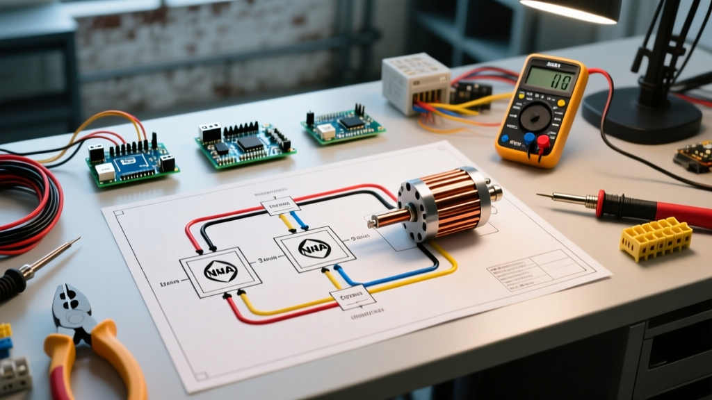
Before terminating any conductors, technicians must differentiate between NEMA (National Electrical Manufacturers Association) and IEC (International Electrotechnical Commission) schematic symbols. NEMA diagrams, dominant in North America, typically depict the power circuit and the control circuit on the same plane using standardized device numbers (e.g., 'M' for motor starter, 'OL' for overload relay). IEC diagrams separate the main power circuit from the auxiliary control circuit, utilizing alphanumeric designations (e.g., 'KM1' for contactor, 'F2' for thermal overload). According to the National Electrical Manufacturers Association (NEMA MG 1) standard, misidentifying these terminal markings remains a leading cause of improper voltage application during motor retrofits.
Single-Phase Dual-Voltage Motor Wiring: The 115/230V Configuration
Single-phase induction motors, commonly found in fractional to 5HP applications, frequently utilize a dual-voltage design to accommodate both 115V and 230V supplies. A standard capacitor-start motor (such as the ubiquitous Baldor L1406TM 1.5HP model) features a terminal board with leads typically numbered 1, 2, 3, 4, 5, and 8, alongside an unmarked ground stud.
Wiring for 230V Operation
For 230V operation, the internal run windings are wired in series. This configuration halves the current draw compared to 115V, allowing for smaller gauge branch circuit wiring and reducing voltage drop over long conduit runs.
- Line 1 (L1): Connect to terminals 1 and 4.
- Line 2 (L2): Connect to terminals 2, 3, and 5.
- Start Circuit: Terminal 8 is tied directly to terminal 5.
Wiring for 115V Operation
For 115V operation, the run windings are reconfigured in parallel to maintain the required magnetic flux density without saturating the core.
- Line 1 (L1): Connect to terminals 1, 3, and 8.
- Line 2 (L2): Connect to terminals 2, 4, and 5.
Rotation Reversal Protocol: To reverse the direction of a single-phase capacitor-start motor, you must reverse the start winding relative to the run winding. On the standard 1,2,3,4,5,8 terminal board, this is achieved exclusively by swapping the connections of leads 5 and 8. Never swap L1 and L2 at the main power disconnect; this will not change the motor's rotation and creates a severe shock hazard during maintenance.
3-Phase Induction Motor Wiring: 9-Lead Star and Delta Configurations
Three-phase motors dominate industrial environments due to their self-starting torque and superior efficiency. The most common industrial workhorse is the 9-lead dual-voltage (230/460V) 3-phase motor. The internal connections dictate whether the motor operates in a Wye (Star) or Delta configuration. Always consult the specific U.S. Department of Energy Motor Systems Sourcebook guidelines for efficiency derating when operating motors at the lower end of their voltage tolerance.
| Configuration | Voltage | Line Connections (L1, L2, L3) | Internal Jumper Connections | Application Use Case |
|---|---|---|---|---|
| Low-Voltage Delta | 230V | T1 & T9 to L1 T2 & T4 to L2 T3 & T5 to L3 |
T6 & T9 tied T7 & T4 tied T8 & T5 tied |
High starting torque, short conduit runs, heavy inertial loads. |
| High-Voltage Wye (Star) | 460V | T1 to L1 T2 to L2 T3 to L3 |
T4 & T7 tied T5 & T8 tied T6 & T9 tied |
Long conduit runs, reduced current draw, standard industrial plant power. |
Note: The above applies strictly to standard 9-lead motors. If your motor nameplate indicates a 12-lead configuration, it is designed for Wye-Delta starting or part-winding starting, requiring a completely different schematic approach involving multiple contactors.
Forward and Reverse Control Circuit Logic
When an electric motor wiring diagram includes a Forward/Reverse (Fwd/Rev) control scheme, the primary engineering challenge is preventing both the forward and reverse contactors from closing simultaneously. A simultaneous closure results in a catastrophic phase-to-phase short circuit, often destroying the contactors and tripping the main upstream breaker instantaneously.
Electrical and Mechanical Interlocking
Modern control circuits utilize a dual-interlock system. Mechanical interlocking involves a physical plastic or metal lever installed between two adjacent contactors (e.g., Schneider TeSys D-line LA9D09978 interlock block, retailing around $35-$50 in 2026) that physically prevents the armatures from engaging at the same time. Electrical interlocking is achieved in the wiring diagram by wiring the normally closed (NC) auxiliary contact of the forward contactor in series with the reverse contactor's coil, and vice versa.
- Pressing the 'Forward' pushbutton energizes the Forward coil (F).
- The 'F' contactor closes main power contacts and auxiliary holding contacts.
- Simultaneously, the NC auxiliary contact on the 'F' contactor opens, physically breaking the circuit path to the Reverse coil (R).
- To reverse, the operator must press 'Stop', de-energizing 'F', which allows the NC contact to close, restoring the path to 'R'.
Sizing Wire and Overload Protection per NEC 2026
Sizing the branch circuit conductors and overcurrent protection devices (OCPD) for motors does not follow standard lighting or receptacle rules. Under NFPA 70 (National Electrical Code) Article 430, motor circuits require distinct calculations for the conductors, the overload relays, and the short-circuit/ground-fault breakers.
- Conductor Sizing (NEC 430.22): Branch circuit conductors must have an ampacity of not less than 125% of the motor's Full Load Amps (FLA) as listed on the nameplate or NEC Table 430.250.
- Overload Relay Sizing (NEC 430.32): Thermal or solid-state overloads (like the Eaton C440 series, approx. $180) must be set between 115% and 125% of the motor FLA, depending on the service factor (SF).
- Short-Circuit Breaker Sizing (NEC 430.52): The inverse-time circuit breaker can be sized up to 250% of the FLA to accommodate the massive inrush current (Locked Rotor Amps) during startup without nuisance tripping.
| Motor HP (460V 3-Phase) | NEC Table FLA | Min Wire Ampacity (125%) | AWG Size (75°C Cu) | Max Inverse-Time Breaker |
|---|---|---|---|---|
| 3 HP | 4.8A | 6.0A | 14 AWG | 15A |
| 7.5 HP | 11.0A | 13.75A | 12 AWG | 25A |
| 15 HP | 21.0A | 26.25A | 10 AWG | 50A |
| 30 HP | 40.0A | 50.0A | 8 AWG | 100A |
| 50 HP | 65.0A | 81.25A | 4 AWG | 150A |
Advanced Diagnostics: Troubleshooting the Wired Circuit
When a newly wired motor fails to start, hums loudly, or trips the breaker immediately, systematic diagnostics are required. Relying on guesswork leads to replaced components that were never actually faulty.
1. Winding Resistance and Balance Testing
Using a digital multimeter (such as the Fluke 87V, standard industry equipment), measure the phase-to-phase resistance on a 3-phase motor. For a healthy 460V motor, the resistance will be very low (often between 0.5 and 3.0 ohms depending on HP). The critical metric is balance. The resistance variance between T1-T2, T2-T3, and T1-T3 must not exceed 2%. A variance greater than 5% indicates shorted turns within the stator winding, requiring a complete motor rewind or replacement.
2. Insulation Resistance (Megger) Testing
A standard multimeter cannot detect microscopic insulation breakdowns. You must use an Insulation Resistance Tester (Megger) applying 500V DC or 1000V DC between the motor windings and the grounded motor frame. According to IEEE 43 standards, the minimum acceptable insulation resistance for motors rated under 1000V is calculated as (Rated Voltage / 1000) + 1 Megohm. Therefore, a 460V motor must read a minimum of 1.46 Megohms. In practice, a healthy new motor in 2026 should read >100 Megohms. Any reading below 2 Megohms indicates moisture ingress, conductive dust contamination, or thermal degradation of the varnish insulation.
3. Voltage Drop Under Load
If a motor operates but runs hot and draws high current, measure the voltage at the motor terminal box while the motor is running under load. A voltage drop of more than 3% from the main distribution panel to the motor terminals indicates undersized conductors, loose terminations, or corroded contactor contacts. For a 460V system, the voltage at the motor terminals must not drop below 446V during continuous operation.