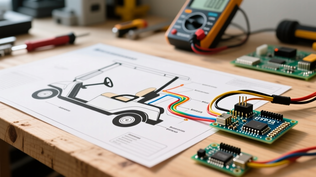

The Diagnostic Truth: Why Schematics Beat Guesswork
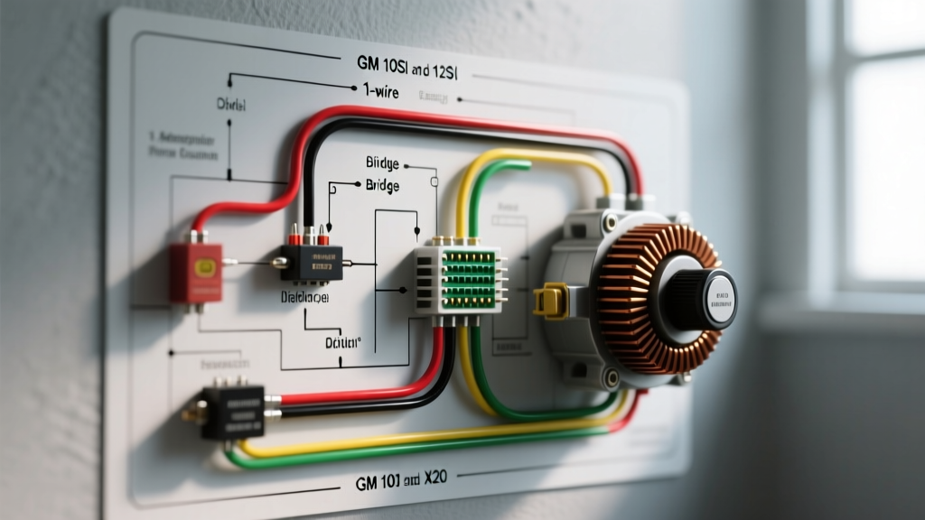
When an electric golf cart refuses to move, emits a continuous solenoid click, or throws a controller rollback code, the instinct for many DIY mechanics is to start swapping expensive parts. This 'shotgun approach' to diagnostics is not only costly but fundamentally flawed. The single most valuable tool in your diagnostic arsenal is the electric golf cart wiring diagram. Whether you are working on a classic 36V EZ-GO TXT Series cart or a modern 48V Club Car Onward equipped with a lithium conversion, the schematic provides the exact logical pathway of electrons from the battery bank to the drive motor.
As of 2026, the landscape of golf cart power has shifted heavily toward 48V LiFePO4 lithium battery retrofits (such as the EcoBattery or RoyPower 105Ah systems, typically costing between $1,200 and $1,500 installed). These modern setups introduce Battery Management Systems (BMS) and CAN-bus communication lines that do not exist on older lead-acid diagrams. Understanding how to read and trace these updated schematics is critical for accurate troubleshooting.
Decoding the Electric Golf Cart Wiring Diagram
Before grabbing a multimeter, you must understand the visual language of the schematic. Golf cart manufacturers use standardized color codes and symbols, though they vary slightly by brand.
Standard Club Car DS & Precedent Color Codes (48V IQ System)
- Red: Main unswitched battery positive (B+).
- Black: Main battery negative / chassis ground (B-).
- Yellow: Forward microswitch signal.
- Green: Reverse microswitch signal.
- White: Solenoid activation coil feed.
- Blue: 12V accessory / key switch output.
Key Schematic Symbols to Identify
Look closely at the solenoid representation on your diagram. You will typically see two large terminals (carrying full pack current, e.g., 48V to 150A) and two small terminals (the activation coil). Modern diagrams will also show a flyback diode wired in parallel across the small coil terminals. This diode prevents voltage spikes from destroying the controller's internal logic board when the solenoid disengages. If your cart exhibits intermittent controller resets immediately after lifting off the throttle, the diagram will point you directly to this diode as a primary suspect.
Step-by-Step Troubleshooting Using the Diagram
Let us apply the wiring diagram to the three most common failure points in a 48V DC/AC golf cart system.
1. The Solenoid Activation Circuit
The solenoid is the heavy-duty relay that connects the battery bank to the motor controller. When you press the throttle, the controller sends a low-current signal to close the solenoid.
Diagnostic Steps:
- Locate the solenoid on your diagram and identify the small activation terminals.
- Set your digital multimeter (DMM) to DC Volts. Connect the black probe to the cart's main negative bus bar and the red probe to the solenoid's activation terminal.
- Turn the key on, place the cart in Forward, and press the throttle. You should read full pack voltage (approx. 48V-52V for lead-acid, or 51.2V-54V for LiFePO4).
- If you read 0V, trace the wire backward on the diagram. Does it route through the Forward microswitch? Does it pass through the OBC (On-Board Computer) or a tow/run switch? The diagram isolates the exact break in the control circuit.
Expert Warning: Never bypass the precharge resistor (typically a 250-ohm, 1/2-watt ceramic resistor shown on the diagram across the large solenoid terminals). This resistor pre-charges the controller's internal capacitors. Bypassing it will cause a massive inrush current that will weld the solenoid contacts shut and instantly destroy the controller's power MOSFETs.
2. Forward and Reverse (F&R) Switch Continuity
If the solenoid clicks but the cart only moves in one direction, the F&R switch is the prime suspect. The wiring diagram reveals that the F&R switch is not a simple toggle; it is a complex mechanical assembly that reverses the polarity of the field coils (in series DC motors) or sends a directional logic signal to the controller (in modern AC induction systems like the Navitas 600A).
Using the diagram, identify the microswitch terminals. With the key off, use your DMM's continuity setting to verify that the Yellow wire (Forward) shows continuity to ground only when the lever is pushed forward. If the mechanical cam inside the F&R housing is worn, the microswitch plunger may not fully depress, resulting in an open circuit that the diagram helps you pinpoint.
3. Throttle Input Verification (MCOR vs. ITS)
The method of reading driver input varies drastically by manufacturer, and your specific electric golf cart wiring diagram will dictate the testing parameters.
- Club Car (MCOR): The Motor Controller Output Regulator uses a 3-wire setup (5V reference, Ground, and Signal). The diagram will show the signal wire sweeping from roughly 0.8V at idle to 3.2V at full throttle. A dead spot in the sweep indicates a failed internal potentiometer.
- EZ-GO (ITS): The Inductive Throttle Sensor uses a magnetic hall-effect setup. It requires an 8V reference from the controller and outputs a varying frequency/voltage. The diagram will highlight the specific controller pins (e.g., J2 connector pins 4 and 5) to back-probe.
Common Failure Modes by Brand & Model
Use the table below to cross-reference your cart's symptoms with the specific circuit paths highlighted in your manufacturer's wiring diagram.
| Brand / Model | Common Symptom | Diagram Trace Point | Typical Repair Cost (2026) |
|---|---|---|---|
| Club Car DS (48V IQ) | Cart beeps 3 times, won't move | Trace OBC to Solenoid white wire; check tow/run switch continuity | $85 - $120 (Switch/Relay) |
| EZ-GO TXT (DC Series) | Cart runs full speed, won't stop | Check solenoid large terminals for continuity with key OFF (welded contacts) | $45 - $75 (Heavy Duty Solenoid) |
| Yamaha Drive (YDRA) | Erratic speed, sudden cutoffs | Trace throttle position sensor (TPS) 5V reference line for voltage drop | $130 - $160 (TPS Assembly) |
| Navitas AC Conversion | Bluetooth app shows 'BMS Fault' | Trace CAN-bus communication harness between BMS and Navitas controller | $40 - $60 (Shielded Comm Cable) |
Essential Tools for Diagram-Based Diagnostics
To effectively execute the tests derived from your schematic, you need the right equipment. Relying on cheap automotive test lights will yield inaccurate results and can damage sensitive logic boards.
- True-RMS Digital Multimeter: Essential for reading the PWM (Pulse Width Modulation) signals sent from the controller to the motor. A high-quality meter like the Fluke 87V provides the accuracy needed to read millivolt drops across the F&R switch.
- Inductive DC Current Clamp: Allows you to measure the amperage draw of the motor without breaking the circuit. If your diagram shows a 400A controller, but your clamp meter reads 450A during acceleration, you have a mechanical binding issue or a failing motor bearing.
- Wire Piercing Probes: Use these sparingly on heavy-gauge wires. Never pierce the insulation on the small 18-AWG control wires, as moisture ingress will cause copper oxidation and future high-resistance faults.
Tracing Intermittent Ground Faults
The most misunderstood aspect of any electric golf cart wiring diagram is the ground return path. Many DIYers assume that because the motor is bolted to the chassis, the chassis is the ground. In modern golf carts, the main negative cable (typically 2 AWG or 1/0 AWG welding cable) routes directly from the battery pack negative terminal to the controller's B- terminal, and then to the motor's A2 terminal.
To troubleshoot a ground fault using the diagram:
- Locate the main negative bus bar on the schematic.
- Set your DMM to DC Volts (millivolt scale if available).
- Place one probe on the motor casing and the other on the battery negative terminal.
- Drive the cart up an incline (under load). According to the National Electrical Code (NEC) principles regarding voltage drop, you should read less than 0.1V to 0.2V across the negative cable. If you read 1.5V or higher, the cable is internally corroded, or the terminal lugs are loose. The controller will interpret this voltage drop as a low-battery condition and initiate a rollback or limp-mode safety cutoff.
Adapting to Lithium Battery BMS Integration
If you are reviewing an updated wiring diagram for a cart that has been converted to lithium, you must pay close attention to the BMS communication loop. As detailed by battery chemistry experts at Battery University, LiFePO4 cells require strict voltage and thermal monitoring. The wiring diagram will show a dedicated 2-pin or 4-pin communication harness connecting the battery BMS to the motor controller. If this wire is pinched, severed, or suffers from a corroded Molex connector, the controller will disable the drive motor to prevent the battery from over-discharging below its critical 2.5V per cell threshold. Always trace this communication loop first when a lithium-converted cart exhibits a 'dead' pedal despite showing a full state-of-charge on the dashboard meter.
Final Diagnostic Protocol
Troubleshooting an electric golf cart is a process of elimination governed by physics and logic. By keeping your specific electric golf cart wiring diagram on hand, systematically verifying voltage at each node, and respecting the safety protocols of high-current DC systems, you can accurately diagnose and repair 95% of all drivetrain faults without resorting to unnecessary part replacement. Always disconnect the main negative battery cable before torqueing any high-amperage terminal lugs to prevent catastrophic short circuits.