
Introduction to 12V Winch Electrical Architecture
Electric winches are high-amperage DC motors that demand rigorous electrical planning. A typical 12,000 lb winch, such as the 2026-standard Warn ZEON 12-S or the Smittybilt XRC GEN2 12K, can pull upwards of 450 amps under maximum stall load. Relying on an inadequate or overly simplified wiring diagram for 12V winch installations leads to catastrophic voltage drops, melted insulation, and potential vehicle fires. This guide provides a comprehensive diagram reference, explaining the exact routing, component selection, and torque specifications required for a fail-safe setup in modern off-road and recovery vehicles.
The Core Wiring Diagram for 12V Winch Systems
When reviewing a standard wiring diagram for 12V winch configurations, the architecture is divided into two distinct circuits: the high-amperage power circuit and the low-amperage control circuit. Understanding the isolation between these two systems is critical for safe operation.
1. The Power Circuit (Battery to Motor)
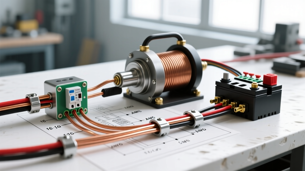
The power circuit carries the massive current required to turn the winch drum. The flow operates as follows:
- Battery Positive (+) to DC Circuit Breaker (Input).
- Circuit Breaker (Output) to Contactor/Solenoid (Main Input Terminal).
- Contactor (Main Output Terminal) to Winch Motor Positive (+).
- Winch Motor Negative (-) returns directly to the Battery Negative (-) or a dedicated, high-capacity chassis ground point.
2. The Control Circuit (The Brains)
The control circuit uses minimal current (typically 2 to 5 amps) to activate the heavy-duty contactor. Modern winches use a sealed control pack containing a microprocessor and relays. The remote control (wired or wireless) sends a signal to the control pack, which then grounds the contactor coil, pulling the heavy copper disc down to bridge the main power terminals.
Wire Gauge and Length Matrix (AWG Selection)
Wire gauge selection is the most common failure point in DIY winch wiring. The total circuit length must be calculated as the round-trip distance (positive cable + negative cable). According to SAE International standards for low-tension automotive cable, you must size the wire based on the maximum stall amperage and total run length to keep voltage drop below 3%.
| Wire Gauge (AWG) | Max Total Run Length | Max Continuous Amperage | Recommended Winch Class |
|---|---|---|---|
| 2 AWG | 0 - 15 feet | 300A | Light Duty (up to 8,000 lbs) |
| 1 AWG | 15 - 25 feet | 350A | Medium Duty (8,000 - 10,000 lbs) |
| 1/0 AWG | 25 - 40 feet | 450A | Heavy Duty (10,000 - 14,000 lbs) |
| 2/0 AWG | 40+ feet | 500A+ | Extreme Duty / Dual Battery Setups |
Contactor vs. Solenoid: Why the Shift?
Older wiring diagrams often reference a standard Ford-style starter solenoid. However, modern heavy-duty winches have transitioned to Albright-style DC contactors.
A standard automotive solenoid is designed for brief cranking bursts (3-5 seconds). A winch contactor is engineered for continuous DC loads, featuring larger copper contact surfaces and internal arc chutes to extinguish the DC spark when the circuit breaks. If you are upgrading an older winch, replacing the factory solenoid with a 400A rated Albright DC contactor (typically costing between $85 and $120) will drastically reduce voltage drop across the switch and prevent the contacts from welding together under heavy load.
Component Deep Dive: Circuit Breakers and Quick Disconnects
Circuit Breaker Sizing
Never wire a winch directly to the battery without overcurrent protection. The National Electrical Code (NFPA 70) and automotive best practices dictate using a DC-rated, surface-mount resettable circuit breaker. For a 12,000 lb winch, a 250-Amp Bussmann 18X series or Blue Sea Systems breaker is mandatory. Do not use standard AC breakers; DC arcs do not cross zero and will destroy an AC breaker instantly.
Anderson SB175 Quick Disconnects
For vehicles where the winch is removable or used on a trailer, integrating an Anderson SB175 plug is highly recommended. These plugs are rated for 175A continuous and can handle the 450A peak surge of a winch motor. When crimping the SB175 contacts, you must use a dedicated hydraulic crimper with a 45-degree indenter die to ensure the copper strands are cold-welded to the terminal, preventing resistance heating.
Step-by-Step Installation Sequence
Follow this precise sequence to ensure mechanical and electrical integrity. Deviating from this order often results in cross-threading or improper torque application.
- Disconnect the Battery: Remove the negative terminal first to eliminate ground fault risks.
- Mount the Circuit Breaker: Position it within 18 inches of the battery positive terminal, as recommended by the American Boat and Yacht Council (ABYC) for DC systems to protect the maximum length of the un-fused cable.
- Route the Cables: Keep positive and negative cables separated by at least 2 inches where possible, and use split-loom tubing to protect against chassis chafing.
- Terminate and Torque: Attach the M8 ring terminals to the winch motor and contactor studs. Use a calibrated inch-pound torque wrench to tighten the nuts to exactly 10-12 Nm (88-106 in-lbs). Over-torquing will snap the brass stud; under-torquing will cause an arc flash.
- Apply Corrosion Inhibitor: After torquing, coat the exposed copper and nuts with Noalox or a heavy dielectric grease to prevent galvanic corrosion.
- Test the Control Circuit: Reconnect the battery and test the winch with no load (spooling out and in) before applying heavy tension.
Common Failure Modes & Troubleshooting Matrix
Even with a perfect wiring diagram for 12V winch setups, environmental factors and mechanical stress can cause failures. Use this matrix to diagnose issues in the field.
- Symptom: Winch clicks rapidly but the drum does not turn.
Diagnosis: Severe voltage drop. The control circuit has enough voltage to pull the contactor, but the voltage drops below 9V when the motor tries to draw current, causing the contactor to drop out repeatedly.
Solution: Check for loose ground connections, corroded battery terminals, or undersized AWG cabling. - Symptom: Winch runs continuously after releasing the remote button.
Diagnosis: Welded contactor contacts. The high-amperage DC arc has melted the copper pads inside the contactor, fusing them together.
Solution: Immediately disconnect the battery. Tap the contactor casing firmly with a rubber mallet to break the weld. Replace the contactor before the next use; do not attempt to reuse it. - Symptom: Circuit breaker trips during light, non-stall pulls.
Diagnosis: Failing winch motor (shorted armature windings) or a seized gearbox causing the motor to draw stall-level amperage even under light loads.
Solution: Bench-test the motor with a multimeter to check for continuity and internal shorts. Rebuild or replace the motor.
Critical Safety Warning: Never use the vehicle's chassis as the primary negative return path for a heavy-duty winch. While chassis grounding works for low-draw accessories, a 400A winch load will overwhelm standard body-to-frame ground straps, potentially welding suspension bushings or frying the vehicle's CAN-bus ECU. Always run a dedicated 1/0 AWG negative cable directly from the winch motor to the battery negative terminal.
Final Considerations for 2026 Winch Tech
As the automotive aftermarket moves toward integrated vehicle management systems in 2026, many new winches (like the latest Warn VR EVO series) feature built-in Bluetooth telemetry and solid-state relays. While the fundamental physics of DC high-amperage wiring remain unchanged, always consult the manufacturer's specific schematic for the control pack pinouts. Ensuring your wire gauge, torque specs, and overcurrent protection meet the rigorous standards outlined above will guarantee your recovery gear performs flawlessly when you need it most.