
The High Stakes of Control Panel Compliance
Designing a motor control center or an industrial automation enclosure is not merely about making the circuit function; it is about ensuring the operator survives a fault condition and the facility avoids catastrophic arc flash events. A properly engineered wiring diagram for control panel assemblies must reflect strict adherence to the National Electrical Code (NEC) and recognized industrial standards. As of the 2026 manufacturing cycle, OSHA inspectors and local Authorities Having Jurisdiction (AHJs) are heavily scrutinizing Short-Circuit Current Ratings (SCCR) and internal wire color coding. Ignorance of these codes is no longer a valid defense, and non-compliant panels are routinely red-tagged, resulting in tens of thousands of dollars in downtime and retrofitting costs.
Decoding the Standards: NEC Article 409 vs. UL 508A
Before drafting your schematic, you must understand the regulatory hierarchy. The NFPA 70 (NEC) Article 409 governs the installation and general requirements of Industrial Control Panels (ICPs). However, the NEC relies on recognized testing standards for the actual construction and component selection. This is where UL 508A comes in.
UL 508A is the Standard for Industrial Control Panels. While the NEC tells you how to connect the panel to the building's power grid, UL 508A dictates how to build the panel itself. If your facility requires a UL Listed panel (often mandated by insurance carriers or OSHA regulations under 1910.303), the shop building it must hold a valid UL 508A listing, which typically costs between $15,000 and $30,000 annually in certification and audit fees. For in-house DIY or maintenance builds, you must still follow UL 508A guidelines to satisfy the NEC's 'approved equipment' clause.
Mandatory Wire Color Codes (NFPA 79 & UL 508A)
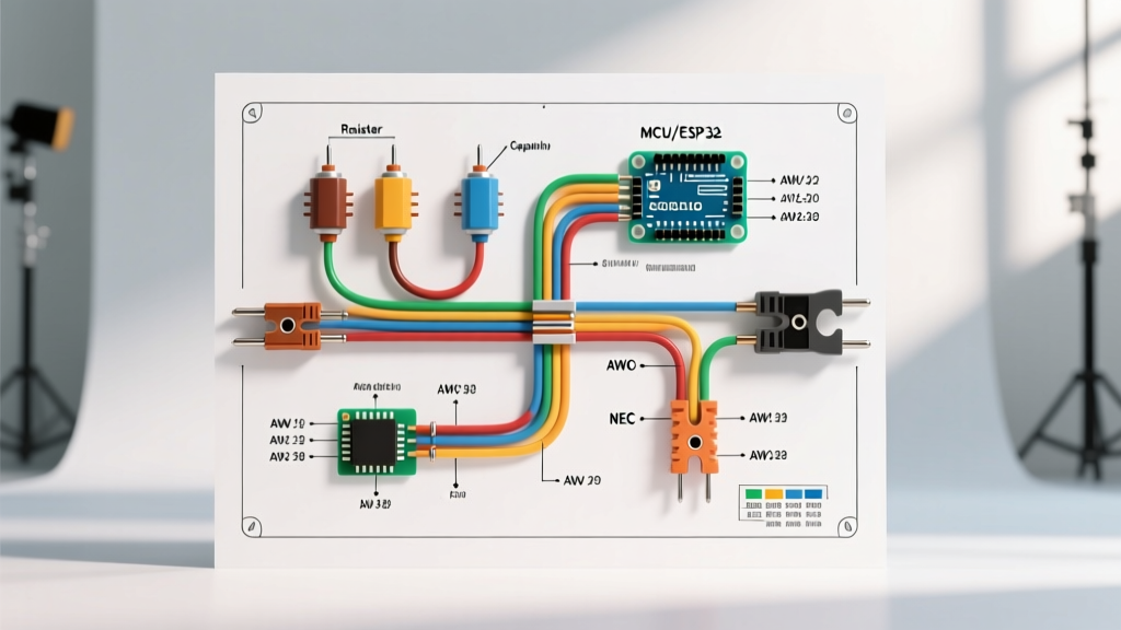
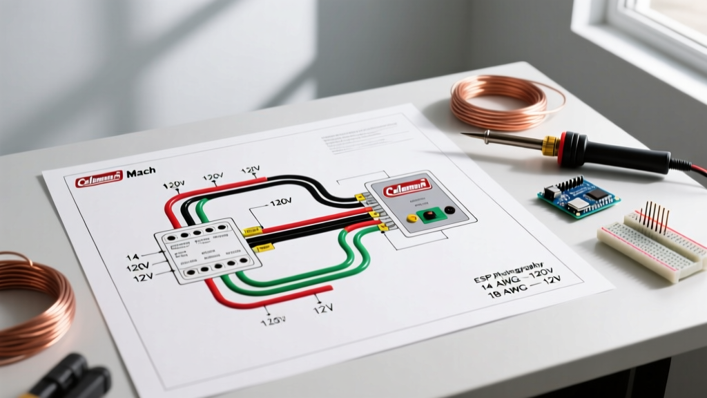
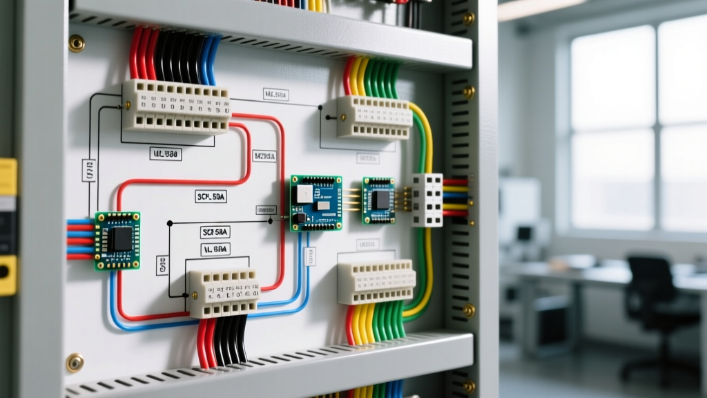
One of the most common reasons a panel fails an AHJ inspection is incorrect wire color coding. A wiring diagram for control panel layouts must explicitly specify insulation colors based on voltage and current type. Mixing a 24V DC signal wire with a 480V AC power wire using the same black insulation is a lethal hazard.
| Insulation Color | Application / Voltage | Code Reference |
|---|---|---|
| Black | 480V AC, 3-Phase or Single-Phase Power | UL 508A 66.1 / NFPA 79 |
| Red | 240V AC Power or Control Circuits | UL 508A 66.1 |
| Blue | DC Control Circuits (typically 24V DC) | UL 508A 66.1 |
| Orange | Unswitched Power (Interlock circuits, external power) | NEC 409.21(B) |
| White / Gray | 120V AC Neutral or Grounded Conductors | NEC Article 200 |
| Green / Green-Yellow | Equipment Grounding Conductor (EGC) | NEC Article 250 |
Calculating Short-Circuit Current Rating (SCCR)
The SCCR is the maximum fault current a panel can safely withstand without causing an arc flash or catastrophic explosion. Many amateur panel builders mistakenly assume the SCCR is simply the interrupting rating of the main circuit breaker (e.g., 65kA). This is a fatal error.
Under UL 508A Supplement SB, the panel's SCCR is dictated by the weakest link in the fault path, unless specific 'series combination' ratings are applied. If you have a 65kA main breaker feeding an Allen-Bradley 100-C09 contactor that is only rated for 10kA, your entire panel SCCR drops to 10kA. If the facility's available fault current is 25kA, the panel is non-compliant and dangerous.
Step-by-Step SCCR Verification
- Determine Available Fault Current: Request the utility transformer data or calculate it using software like SKM Power*Tools for Windows (license costs approx. $4,500).
- Identify the Weakest Component: Check the SCCR rating on every motor starter, VFD, and terminal block in the feeder path.
- Apply Series Combinations: Consult the manufacturer's combination tables (e.g., Schneider Electric or Eaton) to see if pairing a specific breaker with a specific contactor yields a higher tested SCCR (e.g., 50kA).
- Label the Panel: NEC 409.110 requires the SCCR to be permanently marked on the outside of the enclosure.
Grounding, Bonding, and Torque Specifications
NEC Article 250 and UL 508A Section 67 dictate rigorous grounding practices. The equipment grounding conductor (EGC) must be sized according to NEC Table 250.122, based on the rating of the upstream overcurrent protective device, not the load current. For a 100A breaker, you must use a minimum of #8 AWG copper for the ground busbar feed.
Critical Safety Warning: Never mix neutral (grounded) conductors and equipment grounding conductors on the same busbar inside an industrial control panel. This creates parallel neutral paths, causing unpredictable current flow on chassis grounds and guaranteeing nuisance trips on upstream GFCI/RCD devices.
Furthermore, every termination must meet specific torque values. Under-torqued screws on Phoenix Contact CLIPLINE terminal blocks will cause high-resistance connections. Under a 30A continuous load, a loose #10 AWG connection will generate enough heat to melt the insulation and ignite the wireway. Use a calibrated torque screwdriver; standard #10 AWG lugs typically require 12 to 14 in-lbs of torque, while larger #2 AWG lugs may require 45 to 50 in-lbs. Always verify against the manufacturer's spec sheet.
Component Spacing and Creepage Distances
When laying out the backplane for your wiring diagram, physical spacing is just as critical as electrical routing. UL 508A mandates specific 'creepage' (distance across the surface of an insulating material) and 'clearance' (shortest distance through the air) between live parts and grounded metal.
For standard 480V AC circuits (Pollution Degree 2), you must maintain a minimum clearance of 1/2 inch (12.7mm) between uninsulated live busbars and the grounded enclosure walls. If you are using VFDs that generate high-frequency harmonics, increasing this spacing or adding polycarbonate insulating barriers is highly recommended to prevent dielectric breakdown and tracking over time.
Common Failure Modes in Non-Compliant Panels
- Thermal Runaway in Wireways: Failing to apply the 80% continuous load rule (NEC 210.20) results in undersized wire ducts. Overcrowded Panduit wireways trap heat, degrading the PVC insulation and leading to phase-to-ground faults.
- Missing Arc Flash Labels: Failing to calculate incident energy and apply NFPA 70E warning labels on the panel door. This exposes the company to massive OSHA fines (often exceeding $15,000 per violation in 2026) if an electrician is injured.
- Improper Door Interlocks: Using a standard disconnect switch without a mechanical interlock to the panel door. NEC 409.21 requires that the panel door cannot be opened unless the disconnect is in the OFF position, preventing exposure to 480V live busbars.
Frequently Asked Questions
Can I use a DIN-rail terminal block for the main ground connection?
No. UL 508A requires the main equipment grounding connection to be made directly to the enclosure or a dedicated, securely mounted ground busbar. DIN-rail grounding blocks are acceptable for branching internal ground wires, but the primary bonding path from the enclosure to the earth ground must be mechanically robust and not rely on the snap-on friction of a DIN rail.
Does a 24V DC control panel require an SCCR calculation?
Generally, SCCR calculations apply to panels containing power circuits (typically over 50V). However, if your 24V DC panel includes a power supply connected to a 120V/240V AC mains feed, the primary side of that power supply must be factored into the SCCR, and the panel as a whole requires a rating based on the AC input fault current.
For further reading on electrical safety standards and arc flash mitigation, consult the resources provided by UL Solutions and the National Fire Protection Association.