
Why Your Utility Trailer Lights Fail (And How the Diagram Helps)
Utility trailers endure extreme environmental stress. Between road salt, high-pressure car washes, and the physical jarring of uneven terrain, trailer wiring harnesses degrade rapidly. When your running lights flicker or your brake signals fail, guessing which wire to splice is a waste of time. A proper wiring diagram for utility trailer troubleshooting is not just a map of connections; it is a systematic diagnostic flowchart. By cross-referencing your physical symptoms with the schematic, you can isolate high-resistance faults, ground bounces, and converter failures in minutes rather than hours.
According to the National Highway Traffic Safety Administration (NHTSA), proper lighting and reflectivity are critical for collision prevention, yet trailer lighting violations remain one of the most common roadside citations. This guide provides an expert-level diagnostic framework for reading and applying trailer wiring diagrams to solve real-world electrical faults.
The Core Pinouts: 4-Way Flat vs. 7-Way Round
Before touching a multimeter, you must identify your connector standard. Most light-duty utility trailers use a 4-way flat connector, while heavier equipment trailers or those with electric brakes use a 7-way RV/SAE round plug. Misinterpreting the diagram's pinout is the number one cause of cross-wired faults.
| Connector Type | Pin / Position | Wire Color | Function | Min. Wire Gauge (Up to 20ft) |
|---|---|---|---|---|
| 4-Way Flat | Ground (Exposed Pin) | White | Chassis Ground | 16 AWG |
| 4-Way Flat | 1 (Left Male) | Brown | Tail / Running Lights | 18 AWG |
| 4-Way Flat | 2 (Center Male) | Yellow | Left Turn / Stop | 18 AWG |
| 4-Way Flat | 3 (Right Male) | Green | Right Turn / Stop | 18 AWG |
| 7-Way Round | Pin 1 (Center) | Black | 12V Auxiliary Power | 12 AWG |
| 7-Way Round | Pin 2 (Top) | Blue | Electric Brakes | 12 AWG |
The Hidden Culprit: Taillight Converters
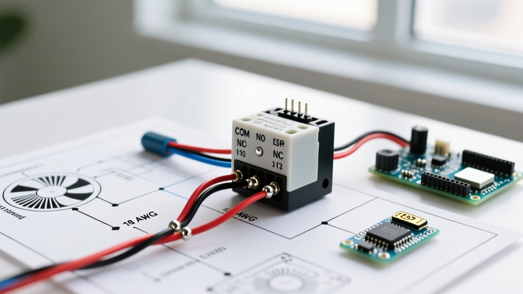
Many modern SUVs and trucks use a 3-wire system (separate bulbs for brake and turn signals), while utility trailers use a 2-wire system (combined brake and turn on the same bulb). If your wiring diagram shows a taillight converter module (like the Curt 56146 or Hopkins 46255) and your trailer lights behave erratically, the converter is your primary suspect.
Expert Diagnostic Tip: If your tow vehicle's left turn signal works, but the trailer's left light stays solid when braking and turning simultaneously, the converter module's internal logic gate has likely failed due to moisture ingress. Bypass the module temporarily with jumper wires to confirm; if the trailer light pulses correctly, replace the converter. Do not attempt to repair potted converter modules.
Step-by-Step Diagnostic Flow Using Your Diagram
When a fault occurs, use your wiring diagram to execute this two-phase testing protocol. Never skip Phase 1, as testing a dead short under load can blow your tow vehicle's ECM or fuse panel.
Phase 1: The Unplugged Continuity Test
- Disconnect the trailer from the tow vehicle to prevent back-feeding voltage into the vehicle's CAN-bus system.
- Set your digital multimeter (DMM) to the Continuity/Ohms setting.
- Place the black probe on the trailer's bare metal chassis (sanding off paint if necessary).
- Use the red probe to test the white ground wire at the connector. A reading above 2.0 ohms indicates internal wire corrosion or a failing ground screw.
- Probe the remaining pins (Brown, Yellow, Green). You should read between 3 to 8 ohms (the resistance of the incandescent bulb filaments). An 'OL' (Open Loop) reading means a broken wire or blown bulb. A reading near 0.0 ohms indicates a dead short to ground.
Phase 2: The Loaded Voltage Drop Test
The Federal Motor Carrier Safety Administration (FMCSA) emphasizes that commercial and heavy-duty lighting must maintain adequate voltage under load. Voltage drop testing is the only way to find high-resistance faults that a simple continuity test will miss.
- Plug the trailer in and turn on the tow vehicle's running lights.
- Set your DMM to DC Volts.
- Place the red probe on the tow vehicle's battery positive terminal and the black probe on the trailer's brown wire at the furthest taillight.
- A healthy circuit will show a voltage drop of less than 0.5V. If your battery reads 12.6V but the trailer wire reads 9.8V, you have a massive 2.8V drop, usually caused by a corroded connector pin or undersized wiring.
The 80% Failure Point: Ground Faults and 'Ground Bounce'
The most misunderstood concept in trailer wiring is the ground return path. Most DIYers assume the white wire is the only ground. In reality, the metal hitch ball and coupler often act as a parallel ground path. When the hitch rusts or loses tension, the electrical load seeks an alternative path to ground, often back-feeding through the running light circuit. This causes 'ground bounce'—where hitting the brakes causes the running lights to dim or flash.
The Permanent Ground Fix
Stop relying on the hitch ball for grounding. Run a dedicated 10 AWG marine-grade tinned copper wire from a clean, bare-metal bolt on the tow vehicle's chassis directly to a clean, sanded bolt on the trailer tongue. Terminate both ends with adhesive-lined heat shrink ring terminals (such as Ancor Marine 12-10 AWG). This ensures the white wire handles 100% of the return load, eliminating ghosting and hyperflashing. Cost for this upgrade is typically under $20 and solves the majority of 'unexplainable' trailer wiring gremlins.
Edge Case: LED Upgrades and Hyperflashing
Upgrading from incandescent to LED trailer lights (e.g., Optronics STL72RB) is a popular 2026 modification for better visibility and lower amp draw. However, LEDs draw so little current that the tow vehicle's flasher relay interprets the circuit as a 'blown bulb' and triggers hyperflashing (blinking twice as fast).
- Solution A (Load Resistors): Install a 6-Ohm, 50W load resistor (like the Curt 57003) in parallel with the LED turn signal wire. Warning: These resistors generate extreme heat and must be mounted to bare metal, away from plastic or wiring.
- Solution B (Smart Relay): Replace the tow vehicle's thermal flasher relay with an electronic, LED-compatible smart relay (e.g., Novita EP35). This is the cleaner, safer, and more modern approach.
Essential Troubleshooting Gear for 2026
To effectively use a wiring diagram for utility trailer diagnostics, you need the right bench tools. Avoid cheap vinyl crimps and standard electrical tape, which fail within months in outdoor environments.
- Curt 58140 7-Way / 4-Way Tester ($18): Plugs directly into the tow vehicle to verify the vehicle-side output before blaming the trailer.
- Hopkins 48125 4-Way Connector ($7): Features a built-in LED indicator on the trailer side for instant visual continuity checks.
- Adhesive-Lined Heat Shrink Butt Splices ($12/pack): When heated, the inner thermoplastic adhesive melts and seals the connection against moisture. This is non-negotiable for trailer wiring.
- Dielectric Grease (Permatex 22058): Apply sparingly to the inside of the plastic connector housing to prevent galvanic corrosion between brass pins. Do not pack the grease so heavily that it prevents the metal pins from making contact.
Summary: Trust the Schematic, Test the Physics
A wiring diagram for utility trailer systems is only as useful as the diagnostic methodology you apply to it. By understanding the pinout standards, isolating the taillight converter, executing proper voltage drop tests, and engineering a dedicated ground return, you can permanently eliminate lighting faults. Always adhere to DOT and NHTSA visibility standards, and prioritize marine-grade, sealed connections to ensure your trailer remains road-legal and safe in all weather conditions.