
The Motor Control Mindset Applied to Workshop Lighting
As specialists in motor wiring and industrial control panels, we typically deal with contactors, variable frequency drives (VFDs), and complex pilot device logic. However, the foundational logic of motor control—specifically 2-wire and 3-wire control circuits using pilot devices—translates directly to commercial and workshop lighting. When an electrician or facility manager searches for a wiring diagram for three way switch with multiple lights, they are essentially looking for a dual-location SPDT (Single Pole, Double Throw) pilot circuit to control a localized load bank.
In a large workshop or warehouse, controlling a bank of high-bay LED fixtures from two distinct locations (such as a main entrance and a rear loading dock) requires the exact same logical sequencing as a remote motor start/stop station. The critical difference lies in the load profile. While a motor starter handles high inductive inrush currents, modern LED arrays present unique capacitive inrush challenges that standard residential switches often fail to handle over time. This guide bridges the gap between standard electrical practices and heavy-duty industrial reliability.
Direct Switching vs. Lighting Contactors: A Load Analysis
Before pulling a single foot of 12/3 NM-B cable, you must calculate the total continuous load. In motor wiring, we never wire a 5HP motor directly through a manual toggle switch; we use a magnetic contactor. The same discipline should apply to large lighting arrays. Standard 15A or 20A three-way wall switches are rated for tungsten and resistive loads, but they degrade rapidly under the high inrush currents of multiple LED drivers.
| Circuit Parameter | Direct 3-Way Switching | 3-Way Pilot + Lighting Contactor |
|---|---|---|
| Maximum Continuous Load | 12A (on a 15A breaker) / 16A (on a 20A breaker) | Up to 20A-30A per pole (e.g., Eaton C4000 series) |
| LED Inrush Tolerance | Poor (Contacts pit and weld over time) | Excellent (Designed for high ballast/driver inrush) |
| Wiring Complexity | Moderate (Line, Load, Travelers) | High (Requires separate 120V coil circuit and dry contacts) |
| Best Application | Small offices, residential hallways, < 8 LED fixtures | High-bay workshops, warehouses, > 10 high-wattage fixtures |
Expert Note: According to Mike Holt Enterprises, a leading authority on the National Electrical Code (NEC), lighting circuits must be calculated as continuous loads if they are expected to remain on for 3 hours or more. This means you must derate your breaker capacity by 125%. A 20A breaker can only safely carry 16A of continuous lighting load.
Step-by-Step: Wiring Diagram for Three Way Switch With Multiple Lights
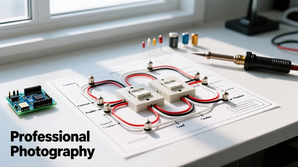
For standard workshop applications where the total continuous load remains under 16A, direct switching is acceptable. Here is the precise sequence for routing power through a 3-way switch pair to a daisy-chained array of multiple lights.
Phase 1: Power Feed to Switch 1 (The Line Side)
- Identify the Common Terminal: On your first 3-way switch (e.g., Leviton 5603-2W), locate the black 'Common' screw. This is your Line input.
- Connect the Hot Feed: Strip 3/4 inch of insulation from the black (hot) wire of your incoming 12/2 NM-B power feed and terminate it under the Common screw. Torque to 14 in-lbs to prevent thermal arcing.
- Neutral and Ground: Splice the incoming white neutral directly to the white neutral running to the light array using a WAGO 221 lever nut. Bond the bare copper ground to the switch yoke and the metal box (if applicable).
Phase 2: Routing the Travelers
The travelers act as the logic pathways between your two pilot devices. You must use 12/3 NM-B (or three individual THHN wires in conduit) between Switch 1 and Switch 2.
- Connect the red and black wires of the 12/3 cable to the two brass 'Traveler' screws on Switch 1. Polarity between these two screws does not matter; they are interchangeable.
- Run the 12/3 cable to the second switch location. Connect the red and black traveler wires to the brass Traveler screws on Switch 2.
- Cap the white wire in the 12/3 cable at both ends. Do not use it as a neutral. Mark it with black electrical tape to indicate it is a spare or future-use conductor, complying with NEC color-coding standards.
Phase 3: Switch 2 to the Light Array (The Load Side)
- Locate the black 'Common' screw on Switch 2. This is your Load output.
- Connect the black wire of a 12/2 NM-B cable to this Common screw. This wire will carry the switched hot to the first light fixture.
- Run the white neutral of this 12/2 cable back to the main neutral splice in Switch 1's box, or route a continuous neutral from the panel if conduit is used.
Phase 4: Daisy Chaining Multiple Lights
To wire multiple lights on this single switched leg, you will daisy-chain them using standard parallel wiring.
- At Fixture 1, connect the incoming switched hot (black) to the fixture's black wire, and splice a third black wire to run to Fixture 2.
- Repeat this black-to-black and white-to-white splicing for all subsequent fixtures.
- Voltage Drop Warning: If your light run exceeds 75 feet, the cumulative resistance on 12 AWG wire may cause a voltage drop exceeding 3%, leading to premature LED driver failure. In these cases, upsize your feed to 10 AWG THHN in conduit.
The 'Motor Control' Method: Using a Lighting Contactor
If you are wiring a massive array of 400W high-bay LEDs, the inrush current can exceed 100A for a few milliseconds, instantly welding the contacts of a standard 20A wall switch. In the motor wiring world, we solve this with a contactor. You can wire your two 3-way switches as low-amperage pilot devices that trigger a Schneider Electric or Eaton lighting contactor coil.
- The Pilot Circuit: Wire the 3-way switches exactly as described above, but instead of feeding the lights, the 'Load' wire from Switch 2 connects to the 'A1' terminal on the lighting contactor's 120V coil.
- The Coil Neutral: Connect the 'A2' terminal on the coil to a dedicated 120V neutral.
- The High-Amperage Load: Feed your main 20A or 30A lighting breaker directly into the Line side (L1) of the contactor's main power poles. Wire the Load side (T1) of the contactor directly to your bank of multiple lights.
This setup ensures your wall switches only carry a fraction of an amp (the coil current), while the heavy-duty silver-alloy contacts inside the contactor handle the brutal LED inrush and continuous amperage. This dramatically increases the lifespan of your installation and aligns with industrial best practices.
NEC Compliance, Grounding, and Safety Standards
When executing any wiring diagram for three way switch with multiple lights, adherence to the National Electrical Code (NEC) is non-negotiable. As highlighted by OSHA's electrical safety guidelines, improper grounding and overloaded neutrals are leading causes of electrical fires in commercial spaces.
- NEC Article 404.2(A): Requires that a grounded circuit conductor (neutral) be provided at every switch location. This is critical if you ever plan to upgrade to smart switches or occupancy sensors, which require standby power.
- NEC Article 250.148: Mandates that equipment grounding conductors be spliced together within the box and connected to the switch yoke. Never use the switch yoke as the sole path for ground continuity.
- Box Fill Calculations (NEC 314.16): A standard single-gang box (18 cubic inches) is often insufficient for a 3-way switch box containing 12/2 feed, 12/3 traveler, and 12/2 load cables. Always use deep 22.5 or 25.5 cubic inch boxes to prevent wire crushing and insulation damage.
Troubleshooting Edge Cases: Ghost Voltage and LED Flicker
In long workshop runs, a common issue when wiring multiple lights on a 3-way circuit is 'ghosting' or faint flickering of the LEDs when the switches are in the OFF position. From a motor control perspective, this is capacitive coupling.
When a long 12/3 traveler cable runs parallel to energized conductors, the alternating magnetic field induces a small 'phantom' voltage (often 20V-40V) on the de-energized traveler. High-impedance digital multimeters will read this as live voltage, and sensitive LED drivers may attempt to charge their internal capacitors, resulting in a periodic strobe effect.
The Fix: Installing a Bleeder Resistor
To eliminate this, wire a 47k-ohm, 2-watt bleeder resistor in parallel with the first light fixture (between the switched hot and the neutral). This provides a path of least resistance for the induced phantom voltage to dissipate, keeping the LED driver completely dark when the circuit is open. This is a standard trick used in industrial control panels to bleed off induced voltages on long pilot-wire runs.
Final Torque and Verification
Before energizing the panel, perform a continuity test with a multimeter to ensure no short circuits exist between the hot travelers and the neutral. Once verified, torque all terminal screws to the manufacturer's specifications (typically 12-16 in-lbs for residential/commercial switches, and up to 35 in-lbs for contactor lugs). A properly executed 3-way lighting circuit, designed with the rigor of a motor control schematic, will provide decades of maintenance-free operation in even the most demanding workshop environments.