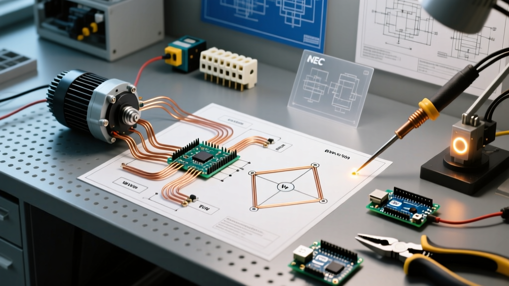

The Definitive Guide to Wiring a Electric Motor
Whether you are retrofitting a workshop air compressor or installing a 3-phase conveyor drive, wiring a electric motor correctly is non-negotiable. A miswired motor will not simply fail to start; it can draw locked-rotor amperage (LRA) indefinitely, melting insulation, destroying windings, and creating severe fire hazards. According to the U.S. Department of Energy, improper electrical connections and voltage imbalances are among the leading causes of premature motor failure in industrial and commercial settings.
This tutorial bypasses generic advice and dives deep into the exact wiring configurations, National Electrical Code (NEC) sizing requirements, and physical termination steps for both single-phase and three-phase induction motors. We will use real-world benchmarks, including the popular Baldor-Reliance L1410T (1.5 HP single-phase) and the Leeson C145T17FB2C (3 HP three-phase) to illustrate our points.
Decoding the Motor Nameplate: Your Wiring Blueprint
Before stripping a single wire, you must interrogate the motor's data plate. The nameplate dictates your wire gauge, breaker size, and overload heater selection. Here are the critical metrics you must extract:
- HP (Horsepower): Dictates the physical frame size and general current draw.
- Voltage (V): Look for dual ratings like 115/230V or 230/460V. This tells you the motor can be reconfigured internally for different supply voltages.
- FLA (Full Load Amps): The current the motor draws at rated load and voltage. This is the number used for overload sizing.
- LRA (Locked Rotor Amps): The massive inrush current during startup (often 600% of FLA). This dictates your short-circuit breaker sizing.
- Duty: Usually 'CONT' (Continuous). If it says '30 MIN', the motor cannot be wired for uninterrupted duty cycles without thermal degradation.
Expert Insight: Never size your branch circuit conductors based on the horsepower rating alone. Always use the specific FLA printed on the nameplate, as high-efficiency (IE3/IE4) motors draw less current than older standard-efficiency models of the same HP.
Single-Phase Motor Wiring: Dual Voltage (115V/230V)
Most residential and light-commercial motors (1/2 HP to 3 HP) are single-phase, capacitor-start/induction-run (CSIR) designs. These motors feature a centrifugal switch that disconnects the start winding once the rotor reaches roughly 75% of synchronous speed.
Step-by-Step: Wiring the Baldor-Reliance L1410T (1.5 HP)
The L1410T is rated for 115/230V. At 115V, the FLA is 10.4A. At 230V, the FLA drops to 5.2A. Always wire for the higher voltage (230V) when possible. Higher voltage halves the current, reducing I²R heat losses in your supply wires and minimizing voltage drop over long conduit runs.
- Access the Peckerhead (Connection Box): Remove the terminal cover. You will typically find 9 numbered leads (T1 through T9) and sometimes unnumbered wires for the thermal protector.
- Configure for 230V (High Voltage): According to standard NEMA wiring diagrams, you must group the run windings in series. Connect T4 to T5, and T8 to T1. This leaves T2, T3, and T9 as your line connections.
- Connect Line Power: Connect your 230V Line 1 (Black) to T2 and T3 (joined together). Connect Line 2 (Red/White) to T9. Connect the bare copper ground to the green grounding screw on the motor housing, not to a terminal lead.
- Verify the Start Capacitor: Ensure the start capacitor (usually 100-130 MFD for a 1.5HP motor) is wired in series with the centrifugal switch and the start winding. If the motor hums but won't turn, the start circuit is open.
Three-Phase Motor Wiring: 9-Lead Wye and Delta Configurations
Three-phase motors are simpler internally because they do not require capacitors or centrifugal switches; the rotating magnetic field is inherently generated by the 120-degree phase shift of the power supply. However, wiring a electric motor with 9 leads requires strict adherence to Wye (Star) or Delta diagrams.
Low Voltage vs. High Voltage Wye (Star) Connections
Take the Leeson 3 HP, 230/460V 3-phase motor. The 9 leads represent the ends of three separate internal stator coils.
- Low Voltage (230V) Wye: The coils are connected in parallel. You will join T4, T5, and T6 together and tape them off. Line 1 goes to T1 and T7; Line 2 goes to T2 and T8; Line 3 goes to T3 and T9.
- High Voltage (460V) Wye: The coils are connected in series. You join T4 to T7, T5 to T8, and T6 to T9. Line 1 connects to T1, Line 2 to T2, and Line 3 to T3.
Reversing Rotation: If the motor spins backward (e.g., a centrifugal pump running in reverse), simply swap any two of the three line leads (e.g., swap L1 and L2). Never swap internal T-leads to reverse direction.
NEC Sizing: Breakers, Overloads, and Wire Gauge
The National Electrical Code (NEC) Article 430 governs motor circuits. A common, dangerous mistake is sizing the breaker like a standard lighting circuit. Motor breakers must handle the massive LRA inrush without tripping, while the overload relay protects the motor from running overcurrent.
For comprehensive code compliance, always refer to the latest NFPA 70 National Electrical Code standards, specifically Articles 430.22 (Conductor sizing), 430.32 (Overload sizing), and 430.52 (Short-circuit protection).
Motor Circuit Sizing Matrix (Copper THHN, 75°C Column)
| Motor HP | Voltage / Phase | Nameplate FLA (Approx) | Min Wire Gauge (125% FLA) | Max Inverse Time Breaker (250% FLA) | Overload Heater Setting (115% FLA) |
|---|---|---|---|---|---|
| 1 HP | 230V / 1-Phase | 5.0A | 14 AWG | 15A | 5.75A |
| 1.5 HP | 230V / 1-Phase | 10.4A | 12 AWG | 30A | 11.96A |
| 3 HP | 230V / 3-Phase | 8.0A | 14 AWG | 20A | 9.20A |
| 5 HP | 460V / 3-Phase | 7.6A | 14 AWG | 20A | 8.74A |
| 10 HP | 460V / 3-Phase | 14.0A | 12 AWG | 35A | 16.10A |
Calculation Example (1.5 HP, 230V Single-Phase):
1. Conductor Sizing (NEC 430.22): 10.4A x 1.25 = 13A. 14 AWG is rated for 15A, but 12 AWG is recommended for mechanical durability and voltage drop mitigation.
2. Breaker Sizing (NEC 430.52): 10.4A x 2.50 = 26A. The next standard breaker size up is 30A.
3. Overload Sizing (NEC 430.32): 10.4A x 1.15 = 11.96A. Set your thermal overload dial or select your bimetallic heater block accordingly.
Troubleshooting Common Wiring Faults
Even experienced electricians make termination errors. Adherencing to OSHA electrical safety guidelines, always lock out and tag out (LOTO) the disconnect before testing continuity. Here is a diagnostic matrix for post-wiring anomalies:
Fault Diagnosis Matrix
- Symptom: Motor hums loudly, draws high current, but will not rotate.
Cause: Single-phasing in a 3-phase motor (one line lead is disconnected), or a failed start capacitor/centrifugal switch in a single-phase motor. The motor is stuck in a locked-rotor state. - Symptom: Motor starts but trips the breaker after 5-10 seconds.
Cause: The centrifugal switch is stuck closed, keeping the start winding engaged. The start winding is not designed for continuous duty and will rapidly overheat, tripping the thermal overload or branch breaker. - Symptom: Motor runs, but gets excessively hot under light load.
Cause: Incorrect voltage tap configuration. Wiring a 230V motor to a 115V supply without reconfiguring the internal T-leads will cause the motor to draw double the expected current to maintain torque, saturating the core and generating massive heat. - Symptom: 3-Phase motor vibrates violently and sounds rough.
Cause: Voltage imbalance across the three phases. A mere 2% voltage imbalance can cause a 20% temperature rise in the motor windings. Check all three line-to-line voltages at the contactor terminals under load.
Final Termination Best Practices
When terminating wires inside the motor peckerhead, use ring terminals crimped with a calibrated ratcheting tool. Do not use fork terminals, as vibration can work them loose from under the terminal nuts. Apply a torque wrench to the terminal nuts; a loose connection increases resistance, which creates localized heating (I²R losses) that will eventually melt the terminal block and cause an arc flash. Finally, ensure the conduit hub is sealed with a proper Myers hub to prevent moisture ingress, which is the silent killer of motor insulation resistance.