
Understanding Your Submersible Pump Wiring Architecture
When installing a deep well system, interpreting the correct wiring diagram for submersible pump configurations is the difference between a reliable water supply and a catastrophic motor burnout. Unlike shallow jet pumps, submersible units operate hundreds of feet underground, meaning every connection must be waterproof, mechanically robust, and electrically precise. According to the National Electrical Code (NEC) Article 430, motors require specific overcurrent protection and wire ampacity calculations that differ from standard household branch circuits.
Before pulling any wire, you must identify whether your system utilizes a 2-wire or 3-wire motor architecture. This fundamentally changes your wiring diagram and control layout.
2-Wire vs. 3-Wire Systems
- 2-Wire Motors: The starting capacitor, relay, and overload protection are sealed inside the motor housing underwater. You only run two power conductors plus a ground. While easier to wire, if a starting component fails, the entire motor must be pulled from the well.
- 3-Wire Motors: The starting components are housed in an above-ground control box (such as the Franklin Electric BPD series). You run three power conductors (Black, Yellow, Red) plus a ground. This is the industry standard for motors 1 HP and above, as it allows for easy component replacement and better voltage management over long distances.
Wire Sizing Matrix: Depth, HP, and Voltage
Voltage drop is the silent killer of submersible motors. If the voltage at the motor terminals drops below 10% of the nameplate rating under load, the motor will overheat and the windings will fail. Always size your drop cable based on the total distance from the control box to the motor, not just the well depth. The following matrix applies to 230V, single-phase systems using copper THWN/UF-B cable.
| Motor HP | Max Distance (ft) | Minimum Wire Gauge (AWG) | Breaker Size (Amps) |
|---|---|---|---|
| 1/2 HP | 200 ft | 14 AWG | 15A |
| 1/2 HP | 450 ft | 12 AWG | 15A |
| 1 HP | 250 ft | 12 AWG | 20A |
| 1 HP | 550 ft | 10 AWG | 20A |
| 1.5 HP | 350 ft | 10 AWG | 25A |
| 2 HP | 250 ft | 10 AWG | 30A |
| 2 HP | 500 ft | 8 AWG | 30A |
Expert Note on Breaker Sizing: NEC 430.52 dictates that the inverse-time circuit breaker for a motor can be sized up to 250% of the motor's Full Load Amps (FLA) to accommodate the massive inrush current during startup. For a 1 HP motor with an FLA of 7.5A, 7.5 x 2.5 = 18.75A. The next standard breaker size up is 20A. Never use a standard residential breaker without verifying it is an HACR (Heating, Air Conditioning, and Refrigeration) rated type.
Step-by-Step Wiring Walkthrough
Follow this exact sequence to ensure a code-compliant and long-lasting installation. For this walkthrough, we are assuming a standard 3-wire, 230V system with an above-ground control box.
Step 1: The Underwater Splice (The Most Critical Step)
Never use standard electrical tape or basic heat shrink for the splice between the motor pigtail and the drop cable. Water intrusion here will destroy a $1,500 motor.
- Prep the Cable: Strip 3/4 inch of insulation from the motor leads and the drop cable. Stagger your cuts by 2 inches so the bare copper connections do not sit parallel to one another, preventing capacitive coupling and short circuits.
- Crimp and Solder: Use copper crimp sleeves, then tin the connection with rosin-core solder for mechanical and electrical permanence.
- Resin Encapsulation: Use a 3M Scotchcast 82-A or equivalent polyurethane resin splice kit. Snap the mold over the staggered splices, mix the two-part resin, and pour it into the cavity. Allow 45 minutes to cure. This provides a dielectric strength exceeding 20kV and a completely waterproof seal.
Step 2: Routing Through the Pitless Adapter
As you lower the pump, secure the drop cable to the polyethylene or PVC well pipe using UV-resistant zip ties or stainless steel clamps every 10 feet. When the pipe reaches the pitless adapter, route the cable through the dedicated side port. Ensure the cable is not pinched between the O-ring and the brass seat of the pitless adapter, as this will slice the insulation over time and cause a ground fault.
Step 3: Wiring the Control Box
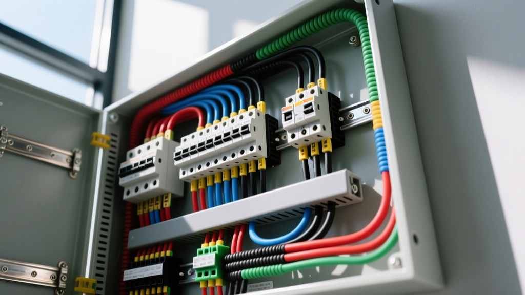
Open your Franklin Electric or equivalent control box. You will see a terminal block labeled L1, L2, Yellow, Red, Black, and Ground.
- Line In (L1/L2): Connect the 230V power feed from your main panel here.
- Motor Leads: Connect the Black, Yellow, and Red drop cables to their identically colored terminals. Reversing these will not reverse the motor rotation (submersible pumps use 3-phase or specific single-phase start/run winding logic that prevents reverse rotation), but it will bypass the start capacitor and instantly burn out the start winding.
- Grounding: Terminate the bare copper equipment grounding conductor to the grounding bus bar. Per Penn State Extension guidelines on private water systems, the well casing must also be bonded to this grounding system using a #6 AWG solid copper wire and an acorn ground clamp.
Step 4: Installing Dry-Run Protection
Modern installations should never rely solely on the pressure switch. If the well runs dry, the pump will overheat in minutes. Wire a Franklin Electric QD (Quick Disconnect) relay or a Cycle Sensor in series with the pressure switch control circuit. These devices monitor the power factor or amperage draw; if the pump starts pumping air (which drastically drops the amperage), the sensor cuts power to the contactor, saving the motor.
Pre-Startup Testing and Troubleshooting Matrix
Before throwing the 230V breaker, you must verify the integrity of your wiring diagram and connections. Use a Megohmmeter (Megger) to test the insulation resistance between each motor lead and the ground wire. Apply 500V DC for one minute. A healthy submersible motor will read greater than 20 Megohms. If it reads below 5 Megohms, you have a compromised splice or damaged cable insulation—do not energize the system.
Common Failure Modes Post-Installation
| Symptom | Probable Cause | Diagnostic Action |
|---|---|---|
| Motor hums, breaker trips after 3 seconds | Start capacitor failure or stuck centrifugal switch in control box. | Test capacitor with multimeter (should read 45-55 µF for 1HP). Check relay contacts for pitting. |
| Pump runs continuously, low pressure | Worn impellers, leaking check valve, or dry well. | Check amp draw. If amps are significantly below FLA, pump is cavitating or running dry. Check well recovery rate. |
| Breaker trips instantly upon contactor engagement | Dead short in drop cable or water intrusion in motor seal. | Megger test all three legs to ground. Inspect pitless adapter pass-through for pinched cable. |
Final Inspection and Code Compliance
Once the system is pressurized and running, verify the running amperage with a clamp meter. It should be within 10% of the motor's nameplate Service Factor Amps (SFA). Ensure the control box is mounted in a location protected from direct weather and UV degradation, as specified by the manufacturer's installation guidelines. A properly executed wiring diagram for your submersible pump, combined with high-quality resin splices and correct NEC breaker sizing, will yield a maintenance-free water system for 15 to 20 years.