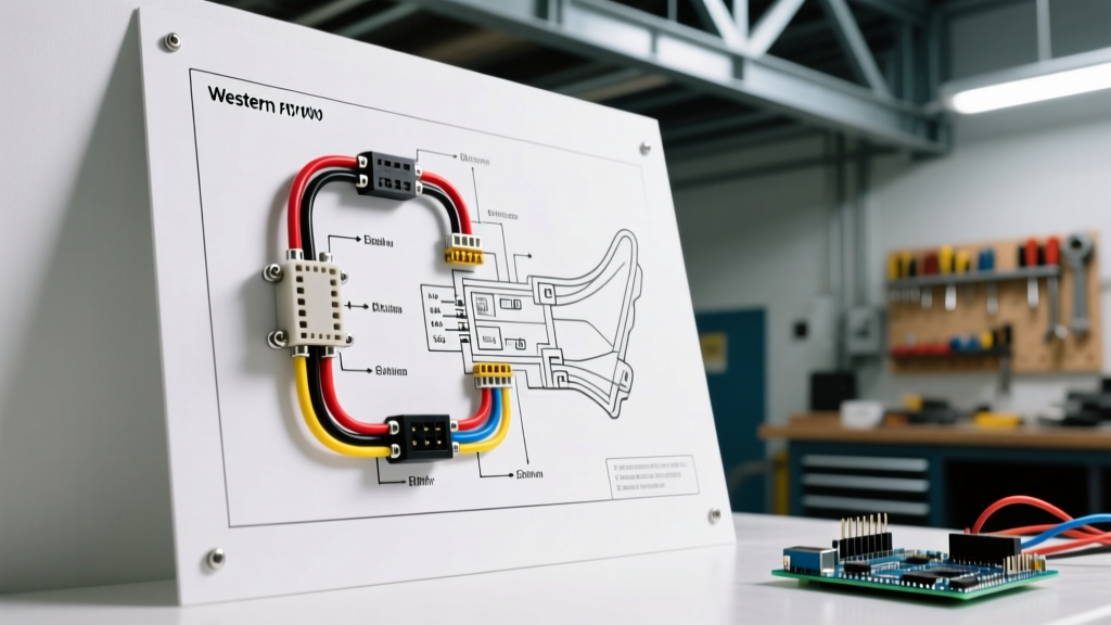

Understanding Western Snow Plow Electrical Architectures
Interpreting a wiring diagram for Western snow plow systems requires a dual understanding of high-amperage hydraulic demands and modern vehicle CAN-bus (Controller Area Network) limitations. Whether you are outfitting a 2026 Ford Super Duty or retrofitting an older Chevy Silverado 2500HD, Western's electrical ecosystems generally fall into two categories: the legacy relay-based systems (often utilizing 3-plug or 4-plug setups) and the modern Fleet Flex Multiplex architecture.
The Fleet Flex system drastically reduces the physical wiring harness by sending digital multiplex signals over a single data line rather than individual copper runs for every solenoid and light circuit. This guide breaks down the exact pinouts, vehicle-specific integration points, and heavy-duty power routing required for a flawless, weatherproof installation.
Core Wiring Diagram for Western Snow Plow Configurations
Before routing wires through the firewall, you must identify your specific Western control module. The most common modern configuration is the 2-plug Fleet Flex system (one heavy-duty power plug, one multiplex control/lighting plug). Older models may use a 3-plug setup separating power, lighting, and control.
Standard 13-Pin Lighting & Control Pinout Matrix
For setups utilizing the traditional 13-pin connector (common on Ultramount and older MVP models), the wiring diagram follows a strict color-code standard. Referencing Western Plows Official Support Literature, the standard pinout is as follows:
| Pin | Function | Wire Color | Gauge / Notes |
|---|---|---|---|
| 1 | Ground | White | 10 AWG (Heavy Ground) |
| 2 | Marker / Clearance Lights | Brown | 14 AWG |
| 3 | Left Turn / Brake | Yellow | 14 AWG |
| 4 | Right Turn / Brake | Green | 14 AWG |
| 5 | Headlights (Low Beam) | Blue | 12 AWG |
| 6 | Headlights (High Beam) | Red | 12 AWG |
| 7 | Backup Lights | Black | 14 AWG |
| 8 | Plow Control Data (Multiplex) | Orange | 18 AWG Shielded |
| 9 | 12V Accessory / Cab Light | Purple | 14 AWG |
| 10-13 | Reserved / Aux Hydraulics | Varies | Per specific wing box |
Vehicle-Specific Routing: Ford, Chevy, and Ram
A generic wiring diagram will fail if it ignores the host truck's Body Control Module (BCM) and upfitter interfaces. Modern trucks actively monitor voltage drops and will throw CEL (Check Engine Light) codes or shut down circuits if they detect the massive inrush current of a plow motor. Here is how to adapt the wiring diagram for the big three HD platforms.
Ford Super Duty (2020-2026 Platforms)
Ford's Upfitter Interface Module (UIM) and dual-alternator setups require careful integration. Do not tap directly into the BCM for cab control power. Instead, route the Western cab control ignition wire to the Upfitter Switch auxiliary output located under the dash (usually a 30-amp or 40-amp rated blunt-cut wire). This prevents the Ford BCM from detecting an 'over-current' fault when the plow's hydraulic pump engages. Ensure the main 2 AWG power wire is fused at 150A within 18 inches of the passenger-side battery positive terminal.
Chevy Silverado / Sierra HD (RPO VYU Prep Package)
GM trucks equipped with the RPO VYU Snow Plow Prep Package include a dedicated 120A+ alternator and pre-routed blunt-cut wires under the hood. The wiring diagram for Western plows on GM HDs dictates using the factory-provided red (power) and black (ground) auxiliary lugs in the underhood fuse block. Critical Edge Case: On 2024-2026 GM HDs, you must use a Western-approved CAN-bus isolation module. Tapping directly into the GM headlight PWM (Pulse Width Modulation) signals without an isolation relay will fry the truck's lighting control module, resulting in a $600+ replacement bill.
Ram 2500/3500 Heavy Duty
Ram trucks utilize a centralized Power Distribution Center (PDC) and a highly sensitive TIPM (Totally Integrated Power Module). Never draw plow control power from the TIPM interior fuses. Route the main 2 AWG power cable to the dedicated auxiliary battery stud located on the passenger side firewall or directly to the primary battery. Use the Ram auxiliary switch bank (if equipped) for the cab controller's 12V wake-up signal.
Step-by-Step Heavy-Duty Power and Ground Execution
The most common cause of plow failure is not a bad motor, but voltage drop due to poor wiring execution. Follow these exact specifications for the power and ground loops:
- Wire Selection: Use only stranded, oxygen-free copper (OFC) wire. Avoid CCA (Copper-Clad Aluminum) which is prone to snapping under hood vibration. Use 2 AWG for runs up to 15 feet; upgrade to 1/0 AWG for extended crew-cab or dually configurations.
- Termination: Crimp all terminals using a hydraulic hex-crimper. Solder is strictly prohibited for high-amperage automotive underhood connections as it becomes brittle and cracks under thermal cycling.
- Weatherproofing: Seal every connection with 3M FP-301 adhesive-lined marine heat shrink. Standard electrical tape will degrade and allow capillary action to wick moisture into the copper strands within one winter season.
- The Ground Path: The ground is just as critical as the power. Bolt the 2 AWG ground cable directly to the engine block or a dedicated, unpainted chassis ground stud. Use a star washer to bite through any factory e-coat or paint.
Advanced Troubleshooting and Edge Cases
When your plow fails to respond, bypass the joystick and read the diagnostic LED on the Western control module (usually located under the hood near the solenoid). According to industry diagnostics tracked by Snow Plow News, the flash codes indicate specific circuit faults:
- 1 Flash: Solenoid short circuit. Check the valve coil wiring for pinched insulation.
- 2 Flashes: Motor short or ground fault. Test the motor brushes and ensure the motor casing is not grounding against the truck frame.
- 3 Flashes: Data line communication loss. Inspect the multiplex data wire (Pin 8) for corrosion or severed copper.
- Continuous Flash: Low voltage supply. Perform a voltage drop test.
Performing a Voltage Drop Test
Do not rely on a simple continuity test. Set your multimeter to DC Volts. Place the red probe on the battery positive post and the black probe on the plow motor positive stud while a helper activates the plow. A reading above 0.2V indicates excessive resistance in the power cable, solenoid, or crimps. Repeat on the ground side (motor casing to battery negative); a reading above 0.1V means your ground connection is failing under load.
Expert Warning: Always disconnect the negative battery terminal before altering any wiring near the alternator or starter. A dropped wrench or stray wire strand bridging the main power lug to the engine block will instantly weld metal and can cause catastrophic lithium-ion or AGM battery venting.
Final Integration and Maintenance
Once the wiring diagram for your Western snow plow is fully executed, apply a coat of dielectric grease (such as Nyogel 760G) to all multi-pin connectors before mating them. This prevents galvanic corrosion between dissimilar metals and repels road salt spray. For comprehensive vehicle-specific harness adapters and up-to-date multiplex firmware updates, always cross-reference your truck's VIN with etrailer's Wiring FAQ and Fit Guide or your local Western distributor's portal.
By adhering to exact wire gauges, respecting modern BCM limitations, and utilizing proper adhesive-lined terminations, your Western snow plow electrical system will deliver reliable, high-speed hydraulic performance through the harshest 2026 winter conditions.