
Why Hardwired Interconnected Alarms Are the 2026 Standard
When it comes to residential life safety, battery-operated units are no longer sufficient for new construction or major renovations. According to the National Fire Protection Association (NFPA), interconnected hardwired smoke alarms provide the earliest possible warning, ensuring that if a fire starts in the basement, the alarm in the second-floor bedroom will sound simultaneously. In 2026, building codes universally mandate that all new dwelling units feature 120V AC hardwired smoke detectors with battery backup and interconnect capabilities.
This comprehensive appliance wiring tutorial breaks down the exact wiring diagram for hard wired smoke detectors, detailing the 14/3 NM-B cable routing, interconnect signaling, and National Electrical Code (NEC) compliance requirements. Whether you are wiring a single-story ranch or a multi-level home, mastering this circuit is essential for any electrical DIYer or professional.
Essential Tools and Material Costs
Before pulling any wire, you need to gather the correct materials. Hardwired smoke alarms require specific cable types to handle both the 120V power and the low-voltage interconnect signal safely.
- Cable: 14/3 NM-B (Romex) with ground. A 250-foot roll of Southwire 14/3 costs approximately $45 to $55 in 2026. The third conductor (usually red) is critical for the interconnect loop.
- Smoke Alarms: Popular 2026 models include the Kidde i12060 (approx. $18/unit) and the First Alert SA9120BKT (approx. $22/unit). Always buy units with a 10-year sealed lithium battery backup.
- Wire Connectors: Ideal 341 Blue or 339 Red wire nuts for secure pigtailing. Avoid push-in connectors for life-safety circuits; mechanical twist connections are required by most local AHJs (Authority Having Jurisdiction).
- Testing Equipment: A reliable non-contact voltage tester like the Klein Tools NCVT-3 ($25) and a digital multimeter to verify the interconnect signal.
The Core Wiring Diagram for Hard Wired Smoke Detectors
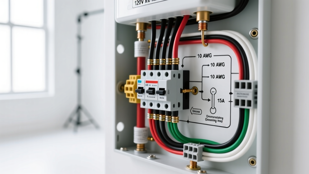
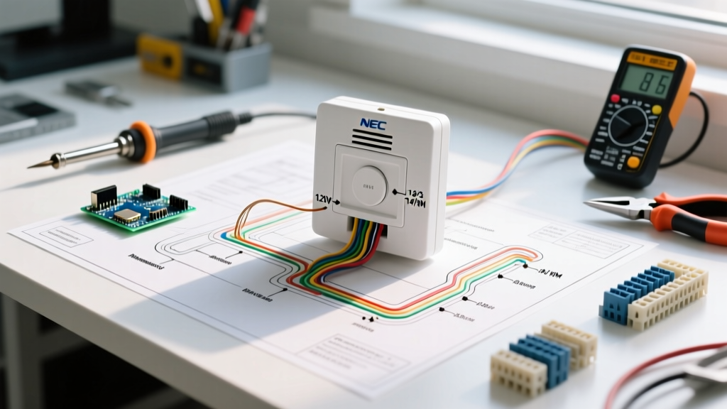
The fundamental wiring diagram for hard wired smoke detectors relies on a daisy-chain topology. Power originates at the main electrical panel, travels to the first smoke alarm, and then continues to subsequent alarms using the 14/3 NM-B cable. The black wire carries the 120V hot, the white wire carries the neutral, the bare copper is the ground, and the red wire serves as the interconnect signaling line.
Expert Warning: Never connect the interconnect wire to a 120V hot source or a neutral bus. Doing so will instantly destroy the internal signaling circuitry of every alarm on the loop and create a severe shock hazard.
Wire Color Mapping and Terminal Functions
| Wire Color (14/3 NM-B) | Terminal / Function | Voltage / Signal Type | Connection Method |
|---|---|---|---|
| Black | Line (Hot) | 120V AC | Pigtail to Alarm Black Wire |
| White | Neutral | 0V (Return) | Pigtail to Alarm White Wire |
| Bare Copper | Ground | 0V (Safety) | Pigtail to Metal Box / Alarm Green |
| Red | Interconnect | 9V DC / Signaling Pulse | Pigtail to Alarm Red/Orange Wire |
Step-by-Step Installation and Interconnect Routing
Follow these precise steps to execute the wiring diagram for hard wired smoke detectors safely and effectively.
- De-energize the Circuit: Turn off the 15A or 20A breaker at the main panel. Use your Klein NCVT-3 to verify zero voltage at the first ceiling junction box.
- Run the 14/3 Cable: Route the 14/3 NM-B from the power source (often a nearby lighting circuit or a dedicated breaker) to the first alarm location, then daisy-chain to the next. Leave at least 8 inches of slack protruding from each electrical box.
- Prepare the Pigtails: Strip 3/4 inch of insulation from all conductors. Create pigtails using 12 AWG or 14 AWG THHN wire for the hot, neutral, and ground to ensure the alarm's factory leads do not bear the mechanical stress of the wire nut connections.
- Connect the Interconnect Loop: This is where most DIYers fail. At each junction box, you will have two red wires (one incoming, one outgoing to the next alarm) plus the alarm's red/orange pigtail. Twist all three together with a Blue Ideal wire nut. If this is the last alarm in the chain, cap the outgoing red wire with a wire nut and tuck it into the box.
- Mount and Test: Secure the mounting bracket to the electrical box using the provided #6-32 screws. Plug the wiring harness into the alarm, twist the unit onto the bracket, and restore power. Press the 'Test' button on the first unit; all interconnected units must sound within 3 seconds.
Critical NEC Code Compliance and AFCI/GFCI Rules
Compliance with the National Electrical Code (NEC) and NFPA 72 is non-negotiable for life safety systems. According to the U.S. Fire Administration (USFA), proper placement and circuit protection are just as important as the wiring itself.
Placement Requirements (NFPA 72)
- Install one smoke alarm inside every sleeping room.
- Install one alarm outside each separate sleeping area, within 21 feet of any bedroom door.
- Install at least one alarm on every level of the dwelling, including basements.
- Mount ceiling alarms at least 4 inches from any wall. If wall-mounted, the top of the alarm must be between 4 and 12 inches from the ceiling.
AFCI and GFCI Exceptions
NEC Article 210.12 requires Arc-Fault Circuit Interrupter (AFCI) protection for all 120V branch circuits supplying outlets in dwelling unit bedrooms. However, hardwired smoke alarms should never be installed on a GFCI-protected circuit, as nuisance tripping could disable the life safety system. While they can be on an AFCI breaker, many local inspectors prefer a dedicated 15A smoke alarm circuit that is clearly labeled at the panel and, where permitted by the local AHJ, exempt from AFCI requirements to prevent arc-fault nuisance trips from disabling fire protection. Always verify with your local building department.
Troubleshooting Common Interconnect Failures
Even with a perfect wiring diagram for hard wired smoke detectors, edge cases and installation errors can cause system faults. Here is how to diagnose the most common 2026 issues:
- All Alarms Chirping Intermittently: This usually indicates a neutral fault or a failing battery backup. Check the white wire connections at every junction box. A loose neutral will cause the alarms to default to battery power, triggering the low-battery chirp.
- One Alarm Sounds, Others Do Not: The interconnect loop is broken. Check the red wire connections at the alarm that is failing to trigger the others. Ensure the outgoing red wire is not accidentally capped off or severed behind the drywall.
- Alarms Sound Randomly Without Fire: This is often caused by the interconnect wire touching a grounded metal box or a bare copper ground wire. The 9V DC signaling pulse will short to ground, which some older alarm logic interprets as a 'trigger' signal. Ensure all red wires are neatly tucked away from bare ground wires.
- Mixed Brand Incompatibility: According to the Consumer Product Safety Commission (CPSC), mixing brands on an interconnect loop can lead to silent failures. Kidde and First Alert use different signaling protocols on their interconnect wires. Always use the exact same brand and model series across the entire daisy-chain.
FAQ: Battery Backup and End-of-Life Indicators
Q: How long do hardwired smoke detectors last?
A: The internal photoelectric or ionization sensors degrade over time. NFPA 72 mandates replacement every 10 years. Modern 2026 units feature an internal chip that triggers an 'End of Life' chirp pattern exactly 10 years from the date of first power-up, regardless of battery status.
Q: Can I add a hardwired alarm to an existing older home without tearing open walls?
A: Yes. If running 14/3 NM-B is impossible, you can use wireless interconnect modules (like the Kidde RF-SM-DC) that communicate via radio frequency. You wire the primary unit to the existing 120V line, and the secondary units run on batteries, bridging the gap between hardwired reliability and retrofit flexibility.