
Upgrading the Predator 212: From Recoil to Electric Start
The Harbor Freight Predator 212cc engine—available in both Non-Hemi (Item #69727) and Hemi (Item #69730) variants—is a cornerstone of DIY motorized projects, from go-karts and mini bikes to log splitters and water pumps. Out of the box, these engines rely on a manual recoil starter. Converting to an electric start requires more than simply bolting on a 12V starter motor; it demands a precise understanding of the predator 212 electric start wiring diagram to safely manage high-amperage cranking loads, low-amperage ignition control, and stator charging circuits.
In this comprehensive motor wiring tutorial, we break down the exact electrical architecture required to reliably start your Predator 212 at the turn of a key. As of 2026, aftermarket electric start kits have become more standardized, but DIY builders must still navigate the critical differences between intermittent and continuous-duty solenoids, alternating current (AC) stator rectification, and magneto kill-switch grounding.
Essential Components & 2026 Pricing Estimates
Before tracing the wiring diagram, you must source the correct hardware. Using undersized wire or incorrect relays is the leading cause of electrical fires in small engine conversions.
- 12V Starter Motor: Must feature the correct pinion gear (typically 18-tooth for the standard Predator 212 flywheel ring gear). Cost: $45–$65.
- Starter Solenoid (Relay): A 12V, 130A+ intermittent-duty solenoid (4-post Ford style or 3-post grounded chassis style). Cost: $15–$25.
- 12V Sealed Lead Acid (SLA) Battery: Minimum 14Ah (e.g., Mighty Max ML14-12) to provide adequate cold cranking amps (CCA). Cost: $35–$50.
- Full-Wave Bridge Rectifier: Required if utilizing the engine's lighting coil to charge the battery (e.g., KBPC3510 35A rating). Cost: $8–$12.
- Ignition Key Switch: A 3-position or 4-position marine-style switch with a dedicated magneto ground terminal. Cost: $15–$22.
The Core Predator 212 Electric Start Wiring Diagram
The electrical system is divided into three distinct circuits. Understanding how these circuits interact is crucial for a clean, reliable installation.
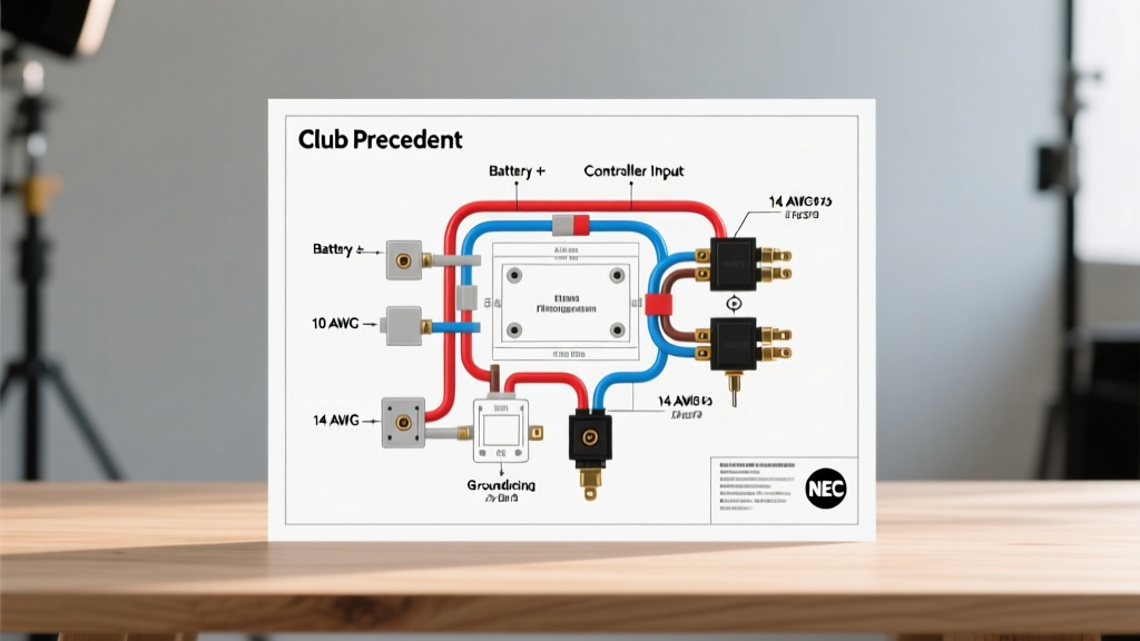
Circuit 1: The High-Amperage Cranking Path
The starter motor on a Predator 212 can draw between 80A and 120A during initial engagement. You must never route this current through a dashboard key switch. Instead, the key switch only triggers the solenoid.
- Battery Positive to Solenoid: Run a heavy-gauge cable (6 AWG) from the battery's positive terminal directly to the large input post on the starter solenoid.
- Solenoid to Starter Motor: Run another 6 AWG cable from the solenoid's large output post to the positive terminal on the starter motor.
- Starter Grounding: The starter motor case must be grounded to the engine block. Ensure the mounting flange is bare metal, free of paint or powder coating. If the engine is isolated from the chassis by rubber motor mounts, run a dedicated 6 AWG ground strap from the starter casing to the battery negative terminal.
- Trigger Wire: Connect a 14 AWG wire from the "Start" terminal of your key switch to the small "S" trigger post on the solenoid. When the key turns to "Start," it sends 12V to the solenoid's internal electromagnet, bridging the two large posts and sending battery power to the starter.
Circuit 2: Ignition, Kill Switch, and Coil Grounding
A common and dangerous mistake in DIY wiring is misunderstanding how the Predator 212's magneto ignition works. The ignition coil generates its own high voltage via magnets on the flywheel. It does not require 12V battery power to create a spark. Instead, the engine is stopped by grounding the primary ignition wire to the engine block.
"If your key switch simply breaks the 12V circuit in the 'Off' position, the engine will continue to run. The switch must actively connect the magneto wire to the chassis ground to kill the spark."
Your marine-style key switch will have a terminal labeled "M" (Magneto). Connect the black wire from the Predator 212's ignition coil to this "M" terminal. In the "Off" position, the switch internally bridges the "M" terminal to the "G" (Ground) terminal, which you must connect to the engine block. In the "On" or "Start" positions, this ground connection is broken, allowing the engine to fire.
Circuit 3: Stator Charging & Rectification
The Predator 212 features an optional lighting coil (stator) under the flywheel. At 3600 RPM, this coil outputs roughly 15V to 18V Alternating Current (AC). You cannot connect this directly to a 12V Direct Current (DC) battery. Doing so will cause severe battery outgassing, boil the electrolyte, and eventually burn out the stator windings.
To safely wire the charging circuit:
- Connect the two AC output wires from the stator to the AC input terminals (marked with a tilde ~) on your full-wave bridge rectifier.
- Connect the positive DC output (+) of the rectifier to the positive terminal of your 12V battery (via a 10A inline fuse).
- Connect the negative DC output (-) of the rectifier to the battery negative or engine ground.
- The battery now acts as a massive capacitor and voltage buffer, absorbing the AC ripple and keeping the system voltage clamped safely around 12.6V to 13.2V.
Wire Gauge & Component Specification Matrix
Adhering to proper wire ampacity standards is non-negotiable to prevent voltage drop and thermal runaway. The following matrix aligns with standard electrical safety practices outlined by the NFPA 70 (National Electrical Code) guidelines for DC low-voltage systems.
| Circuit Path | Recommended Wire Gauge | Max Continuous Amps | Fuse / Breaker Rating |
|---|---|---|---|
| Battery (+) to Solenoid Input | 6 AWG Copper | 150A | 150A ANL Fuse |
| Solenoid Output to Starter (+) | 6 AWG Copper | 150A | None (Protected by main) |
| Main Ground Strap | 6 AWG Copper | 150A | N/A |
| Solenoid Trigger (Key to S-Post) | 14 AWG Copper | 15A | 10A Inline ATC |
| Stator AC to Rectifier | 16 AWG Copper | 10A | N/A |
| Rectifier DC (+) to Battery | 14 AWG Copper | 15A | 10A Inline ATC |
Advanced Troubleshooting & Edge Cases
Even with a perfect diagram, physical installation variables can cause failure. Here is how to diagnose the most common Predator 212 electric start issues using a digital multimeter (DMM).
Solenoid Clicks, But Starter Does Not Turn
This indicates the trigger circuit is working, but the high-amperage path is failing. First, check the battery voltage under load. According to the Battery Council International (BCI) technical standards, a healthy 12V SLA battery should not drop below 10.5V during cranking. If it drops to 8V or lower, the battery has a bad cell or is severely undersized. If battery voltage remains above 11V during the click, the solenoid's internal contacts are likely pitted or carbon-fouled. Replace the solenoid.
Starter Motor Spins, But Engine Does Not Crank
This is a mechanical alignment issue, not an electrical one. The starter's Bendix drive or pinion gear is failing to engage the flywheel's ring gear. Ensure the starter motor is seated flush against the mounting block. If you are using an aftermarket adapter plate, verify that the gear mesh depth is exactly 0.020" to 0.040". Too tight, and the starter will bind; too loose, and it will freewheel.
Engine Will Not Shut Off With Key in "Off" Position
Your magneto kill wire is not achieving a solid ground. Test this by pulling the black wire from the ignition coil and touching it directly to the bare metal of the engine block while the engine is running. If the engine dies immediately, the issue is in your key switch or the ground wire connecting the switch's "G" terminal to the chassis. Clean all grounding points with sandpaper to remove paint and rust.
Safety and Compliance Protocols
When modifying small engines for electric start, always adhere to manufacturer clearances and local safety regulations. The EPA's small engine guidelines remind builders that modifying engine shrouds to fit aftermarket starters can alter cooling airflow, leading to overheating and increased emissions. Never cut or remove the OEM blower housing to make room for a starter motor. Instead, source a starter specifically cast for the Predator 212's OEM mounting footprint. Always disconnect the negative battery terminal before routing new wires, and use heat-shrink butt connectors rather than electrical tape for all outdoor or high-vibration connections to prevent moisture ingress and galvanic corrosion.