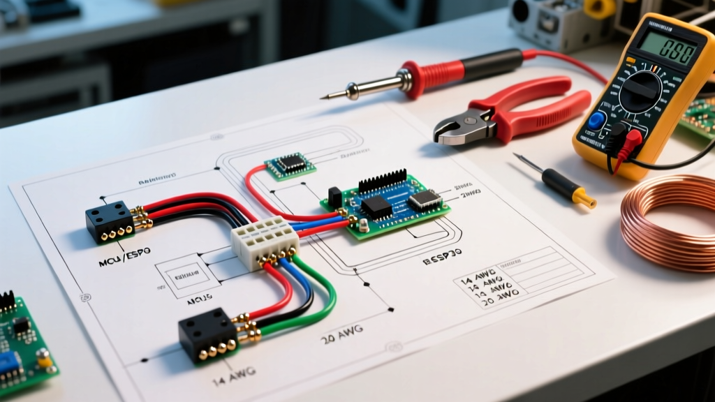

Strategic Planning for Submersible and Jet Pump Electrical Systems
Dropping a pump into a borehole is only half the battle; the electrical infrastructure dictates the system's longevity, efficiency, and safety. When interpreting a wiring diagram for well pump installations, DIYers and professional contractors alike must account for voltage drop, inrush current, and strict National Electrical Code (NEC) grounding mandates. In 2026, with copper prices stabilizing but remaining high, precise wire gauge calculation is more critical than ever to avoid overspending while preventing motor burnout.
This installation planning guide dissects the core electrical components, wire sizing matrices, and control logic required for a flawless well pump deployment.
⚠️ CRITICAL SAFETY WARNING: Submersible well pumps operate on 230V (or 115V for shallow systems), which is lethal. Always verify that the main breaker panel is locked out and tagged out (LOTO) before terminating any connections at the pressure switch or control box. Consult NFPA 70 (National Electrical Code) Article 250 for specific grounding requirements.
Core Components in a Well Pump Wiring Diagram
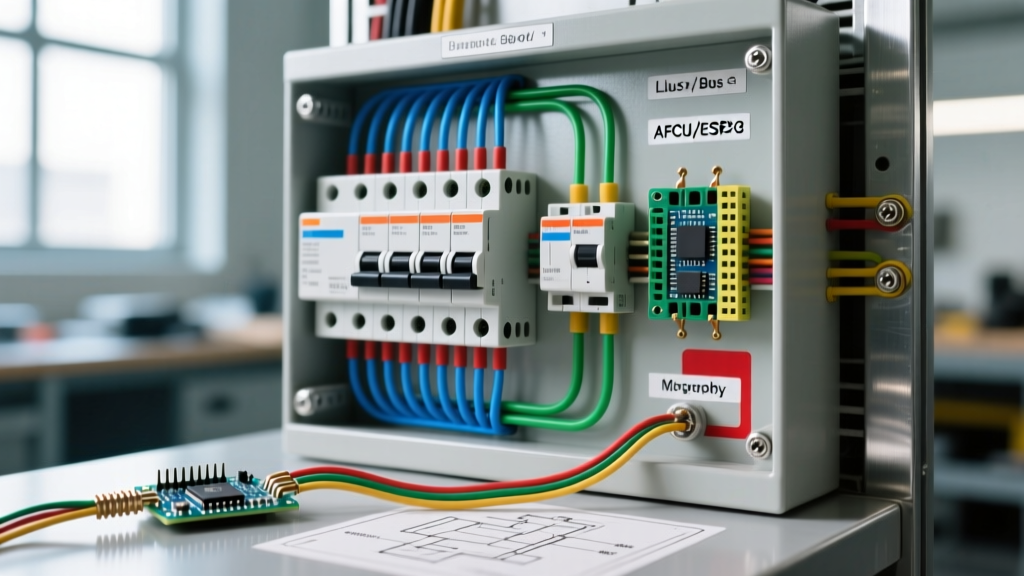
A standard residential well pump circuit consists of four primary nodes. Understanding how these interact is essential before pulling any wire.
- The Main Disconnect / Breaker: A dedicated double-pole breaker (for 230V systems) located in the main service panel.
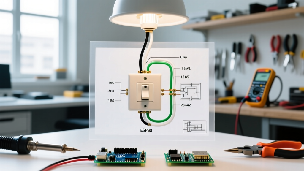
- The Pressure Switch: Typically a Square D Pumptrol FSG2 or equivalent. It monitors system PSI and closes the 230V circuit to call for water.
- The Control Box (3-Wire Systems Only):strong> Houses the start/run capacitors and the heavy-duty relay. It manages the high inrush current required to start the motor.
- The Pump Motor: The submersible or jet pump unit itself, containing the stator windings and rotor.
2-Wire vs. 3-Wire Submersible Pump Architectures
When reviewing your wiring diagram for well pump setups, you must first identify whether you are deploying a 2-wire or 3-wire motor. This decision fundamentally alters your above-ground wiring plan.
| Feature | 2-Wire Submersible Motor | 3-Wire Submersible Motor |
|---|---|---|
| Wiring Configuration | Black (Line 1), Red (Line 2), Green (Ground) | Black, Red, Yellow (Lines), Green (Ground) |
| Capacitor/Relay Location | Internal (sealed inside the motor housing) | External (above-ground control box) |
| Troubleshooting Ease | Difficult (requires pulling the pump to test components) | Easy (test and replace control box components at the surface) |
| Splice Points in WellFewer (lower risk of water ingress at splices) | More (requires a 4-wire splice kit) | |
| Typical Max HP Limit | Usually capped at 1.5 HP to 2 HP | Standard for 3 HP and above |
Wire Sizing and Voltage Drop Calculations
The most common cause of premature well pump failure is voltage drop caused by undersized wire. The NEC recommends a maximum voltage drop of 5% for branch circuits. Because submersible pumps are often located 200 to 500 feet away from the breaker panel (factoring in both horizontal trenching and vertical well depth), you must size the wire based on the total one-way distance, not just the trench length.
AWG Sizing Matrix for 230V Submersible Pumps
The following table provides the maximum one-way cable run (in feet) for standard copper UF-B or THWN wire in conduit, maintaining a < 5% voltage drop at full load amps (FLA).
| Motor HP | 14 AWG Copper | 12 AWG Copper | 10 AWG Copper | 8 AWG Copper | 6 AWG Copper |
|---|---|---|---|---|---|
| 1/2 HP | 220 ft | 360 ft | 580 ft | 920 ft | 1,450 ft |
| 3/4 HP | 140 ft | 230 ft | 370 ft | 590 ft | 940 ft |
| 1.0 HP | 100 ft | 170 ft | 270 ft | 430 ft | 690 ft |
| 1.5 HP | 70 ft | 110 ft | 180 ft | 290 ft | 460 ft |
| 2.0 HP | 50 ft | 80 ft | 130 ft | 210 ft | 340 ft |
Pro-Tip for 2026 Installations: If your total run falls near the upper limit of a wire gauge, always step up to the next size. The cost difference between 10 AWG and 8 AWG THWN wire (roughly $0.40 to $0.70 per foot) is negligible compared to the $1,200+ cost of replacing a burned-out Franklin Electric or Goulds submersible motor.
Underground Splicing: The Weakest Link
Standard wire nuts and electrical tape will fail catastrophically when submerged in a well casing or buried in damp soil. Your wiring diagram must account for waterproof resin-filled splice kits.
- Strip and Connect: Use standard copper crimp connectors or wire nuts for the physical connection.
- Apply Heat Shrink: Slide adhesive-lined marine-grade heat shrink over individual wire connections and apply heat until the adhesive seals the edges.
- Pour the Resin: Use a kit like the Franklin Electric WR (Waterproof Resin) Splice Kit or 3M Scotchcast. Mix the two-part polyurethane resin and pour it into the provided mold, completely encapsulating the splice.
- Cure Time: Allow 30 to 45 minutes for the resin to harden into a solid, waterproof block before lowering the pump.
Pressure Switch Wiring and Calibration
The pressure switch is the brain of the pump circuit. The most ubiquitous model is the Square D Pumptrol FSG2 (typically retailing between $25 and $45). Inside the switch, the 230V line and load wires terminate on four brass screws. The ground wire bypasses the switch and connects directly to the grounding bus or the metal enclosure.
Adjusting the Cut-In and Cut-Out PSI
Most residential systems operate on a 40/60 PSI or 30/50 PSI scale. If your water pressure feels weak, or your pump is short-cycling, you may need to adjust the switch. Under the plastic cover, you will find two nuts:
- The Large Nut (Range Adjustment): Turning this clockwise increases both the cut-in and cut-out pressures equally. (e.g., shifts a 30/50 switch to 40/60).
- The Small Nut (Differential Adjustment): Turning this clockwise increases the gap between cut-in and cut-out. Warning: Adjusting the small nut incorrectly can cause the switch to fail to open, leading to a continuous run condition and destroyed pump.
Grounding and Surge Protection Mandates
According to NEC Article 250.112(l), submersible well pumps require a dedicated equipment grounding conductor. You cannot rely on the metal well casing or the metal drop pipe as the sole ground path. You must pull a dedicated copper ground wire (minimum 12 AWG, though 10 AWG is standard for 30A circuits) all the way from the main panel to the pump motor.
The Case for Transient Voltage Surge Suppressors (TVSS)
Rural well installations are highly susceptible to lightning strikes and grid-switching surges. A surge traveling down the utility lines can instantly vaporize the start winding in a 2-wire pump or blow the relay in a 3-wire control box. Installing a well-rated TVSS (such as the Symcom / Littelfuse SPD120/240, approx. $65) at the pressure switch or main disconnect is a non-negotiable best practice for modern installations. Wire the TVSS in parallel with the load side of the pressure switch.
Common Failure Modes and Edge Cases
Even with a perfect wiring diagram for well pump execution, environmental and mechanical factors can cause issues. Here is how to troubleshoot the most common edge cases:
1. The Pump Hums but Won't Start (3-Wire Systems)
Diagnosis: In a 3-wire system, this almost always indicates a failed start capacitor inside the control box. The start capacitor provides the phase-shifted torque needed to get the motor spinning.
Action: Turn off power, safely discharge the capacitor using an insulated screwdriver across the terminals, and test it with a multimeter capable of reading microfarads (µF). Replace the capacitor (usually $15–$25) if the reading is outside the ±10% tolerance printed on the label.
2. Rapid Short-Cycling
Diagnosis: The pump turns on and off every 10 to 20 seconds. This is rarely an electrical wiring fault; it is usually a waterlogged pressure tank (the internal bladder has ruptured).
Action: Drain the system, check the Schrader valve on the pressure tank for water (if water comes out, the bladder is dead). Replace the tank and recharge the new tank's air pressure to 2 PSI below the switch's cut-in setting (e.g., 38 PSI for a 40/60 switch).
3. Nuisance Breaker Tripping
Diagnosis: The breaker trips immediately upon the pressure switch closing.
Action: This indicates a dead short or a seized motor. Use a megohmmeter (Megger) to test the insulation resistance of the motor windings to ground. A reading below 1 Megohm indicates water has breached the motor seal, requiring a full pump pull and replacement.
Final Planning Checklist
Before trenching and pulling wire, verify the following:
- [ ] Total one-way wire distance calculated (trench + well depth + panel distance).
- [ ] Wire gauge verified against the 5% voltage drop matrix.
- [ ] Dedicated copper equipment ground wire included in the pull.
- [ ] Waterproof resin splice kits purchased for the drop cable connection.
- [ ] TVSS surge protector integrated into the pressure switch enclosure plan.
- [ ] Pressure tank pre-charge pressure verified with a digital tire gauge.
For comprehensive technical manuals, capacitor testing charts, and motor winding resistance tables, always refer to the Franklin Water Technical Resources library, which remains the industry gold standard for submersible motor diagnostics.