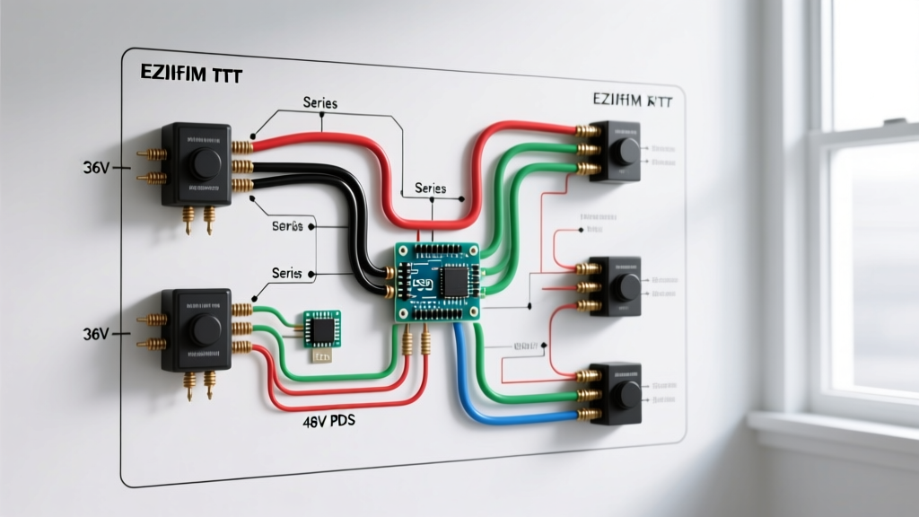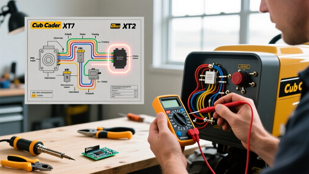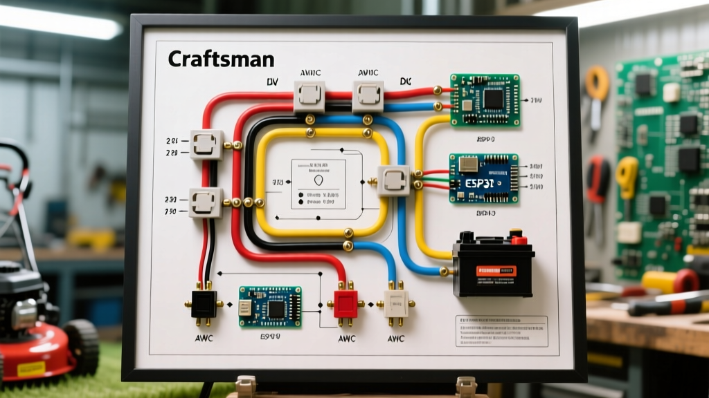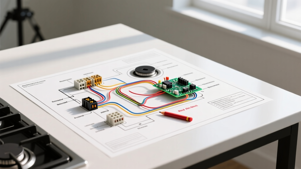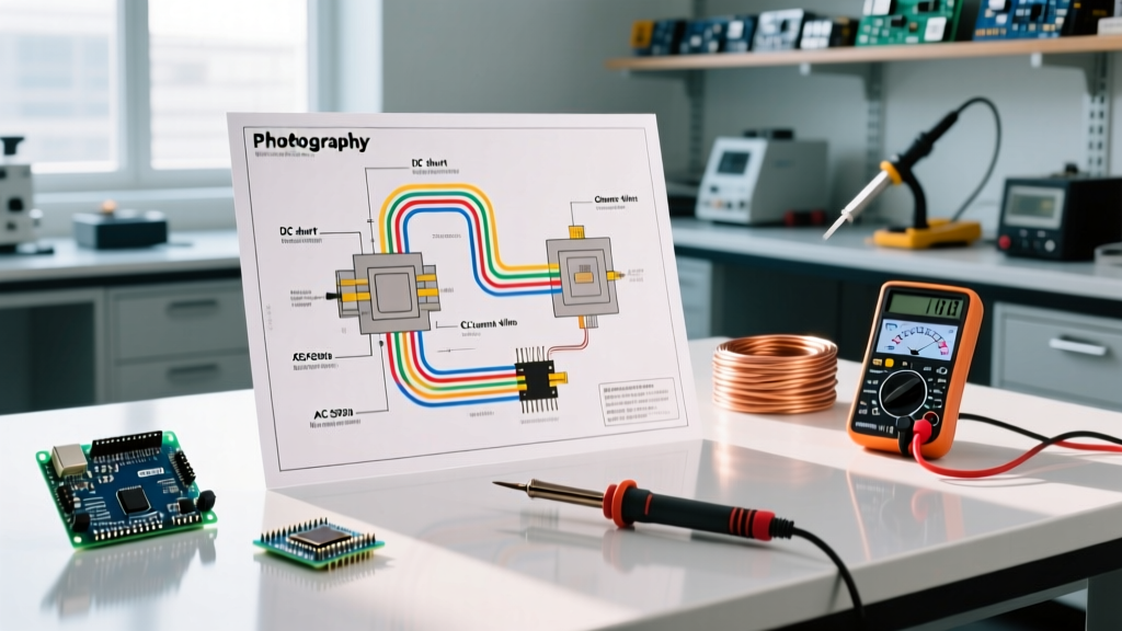

Introduction to Ammeter Wiring Fundamentals
Whether you are monitoring a 12V solar battery bank, troubleshooting a 240V HVAC compressor, or building a custom motor control panel, accurately measuring current flow is non-negotiable. However, interpreting a wiring diagram for ammeter installations can be confusing for DIYers and junior technicians alike. Unlike voltmeters, which are wired in parallel and draw negligible current, ammeters must interact directly with the load path or its magnetic field. A miswired ammeter doesn't just give you bad data; it can melt sense wires, destroy digital panel meters (DPMs), or create lethal arc-flash hazards in AC systems.
In this comprehensive reference guide, we break down the exact wiring topologies for both DC and AC ammeter installations. We will cover direct-wire setups, external shunt configurations, and Current Transformer (CT) wiring, complete with wire gauge specifications, real-world failure modes, and critical safety protocols for 2026 electrical standards.
Core Components of an Ammeter Circuit
Before tracing the lines on a schematic, you must understand the physical hardware involved. Modern digital panel meters (like the popular Bayite or Drok 0-100A models, typically priced between $15 and $25) rarely pass the main load current directly through the meter's PCB. Instead, they rely on external sensors.
- The Meter Head (DPM): The display and logic board. It requires a separate low-current power supply (usually 3.5V to 30V DC) and high-impedance sense inputs.
- The Shunt Resistor (DC): A precision, low-resistance block of manganin or copper alloy that drops a specific millivoltage (usually 50mV or 75mV) at its rated maximum current.
- The Current Transformer (AC): A toroidal magnetic core that steps down high AC primary currents to a safe, measurable secondary current (standardized at 5A or 1A).
DC Ammeter Wiring Diagrams Explained
DC current measurement relies on Ohm's Law (V = I × R). We measure the voltage drop across a known resistance to calculate the current. Depending on your amperage, you will use one of two wiring diagrams.
1. Direct-Wire DC Ammeter (0A to 50A)
For low-current applications like LED lighting circuits or small water pumps, direct-wire digital ammeters are common. In this wiring diagram, the ammeter is placed in series with the load.
- The main positive supply wire enters the ammeter's IN terminal.
- The OUT terminal connects directly to the load's positive terminal.
- The meter's internal shunt handles the entire load current.
Expert Warning: Never use a direct-wire 50A meter for a continuous 45A load. Internal PCB traces and solder joints will overheat. Always apply the 80% NEC continuous load rule; for a 45A continuous load, use a 100A external shunt system.
2. Shunt-Based DC Ammeter (50A to 1000A+)
For high-current applications like EV battery packs, solar inverters, or winches, an external shunt is mandatory. The wiring diagram for this ammeter setup separates the power circuit from the sense circuit.
The Power Circuit: The heavy-gauge battery cable (e.g., 2/0 AWG) passes through the shunt's massive copper terminals. The shunt is wired in series on the negative (ground) side of the battery bank. Wiring on the negative side is preferred in DIY solar and marine applications because it allows the meter's power leads to share a common ground reference with the battery negative, preventing the isolation amplifiers inside the DPM from being overloaded by common-mode voltage.
The Sense Circuit: Two thin, twisted-pair wires connect the inner sense terminals of the shunt to the DPM's signal inputs.
Shunt Math & Heat Dissipation: A standard 500A, 75mV shunt has a resistance of exactly 0.00015 ohms. At peak 500A draw, it dissipates 37.5 Watts of heat (P = V × I). If your wiring diagram places this shunt inside a sealed, unventilated plastic junction box, the manganin alloy will drift in resistance, causing massive measurement errors, or worse, melting the enclosure. Always mount shunts in free air or on a thermal busbar.
AC Ammeter Wiring Diagrams: Using Current Transformers
Measuring Alternating Current requires a completely different approach. You cannot safely break a 240V AC line to insert a shunt. Instead, AC wiring diagrams utilize Current Transformers (CTs). As detailed in foundational electrical engineering texts like All About Circuits, a CT uses electromagnetic induction to isolate the meter from dangerous line voltages.
Standard AC CT Wiring Topology
In a typical 200:5 CT setup, the main AC load wire (the primary) passes through the donut hole of the CT exactly once. The CT's secondary terminals (S1 and S2) are wired directly to the AC ammeter's input terminals using 14 AWG stranded wire.
CRITICAL SAFETY HAZARD: The secondary circuit of a Current Transformer must NEVER be left open while primary current is flowing. If you disconnect the ammeter while the AC load is running, the CT will attempt to drive 5A through an infinite resistance. This causes the core to saturate and induces lethal voltages (often exceeding 3,000V) across the open S1 and S2 terminals, resulting in explosive arc flashes and lethal shock. Always install a shorting block or shorting switch in your wiring diagram if the meter needs to be removed for calibration.
Wire Gauge and Routing Matrix
Signal degradation is the enemy of accurate ammeter readings. The millivolt signals generated by DC shunts are highly susceptible to Electromagnetic Interference (EMI) from adjacent inverter cables or VFD (Variable Frequency Drive) lines. Use the matrix below to select the correct wiring for your sensor connections.
| Sensor Type | Signal Type | Recommended Wire Gauge | Max Run Length | Routing / Shielding Rules |
|---|---|---|---|---|
| DC Shunt (50mV/75mV) | Analog mV (Very Low) | 18 AWG to 16 AWG | 10 Feet | Must be twisted pair. Route away from AC lines. Use shielded cable if near VFDs. |
| DC Hall Effect Sensor | 0-5V Analog / PWM | 20 AWG to 18 AWG | 25 Feet | Standard 3-wire cable (VCC, GND, Signal). Keep away from high-current busbars. |
| AC Current Transformer | AC Current (1A or 5A) | 14 AWG Stranded | 50 Feet | Never use wire nuts; use crimped ferrules and screw terminals. Never fuse the secondary. |
Step-by-Step: Wiring a 500A DC Shunt for a Solar Battery Bank
To provide actionable specificity, here is the exact procedure for wiring a 500A/75mV shunt (such as a Modutek or Simpson model, approx. $35) to a standard digital panel meter in a 48V off-grid solar system.
- Disconnect All Power: Open the battery disconnect switch and verify 0V at the busbars using a CAT III multimeter.
- Mount the Shunt: Bolt the shunt to a non-conductive surface or a dedicated thermal busbar. Ensure the side marked 'BATT' faces the battery negative, and 'LOAD' faces the inverter/charge controller negative.
- Terminate Power Cables: Crimp 2/0 AWG copper lugs onto your battery and load cables. Torque the shunt nuts to the manufacturer's spec (typically 12-15 ft-lbs) to minimize contact resistance.
- Wire the Sense Lines: Strip 18 AWG twisted-pair wire. Connect one wire to the inner set-screw on the 'BATT' side, and the other to the inner set-screw on the 'LOAD' side. Do not place these sense wires under the main 2/0 AWG lugs; the massive crimp lugs will crush the thin sense wires, causing intermittent connections.
- Power the DPM: Connect the DPM's thick red and black power wires to a fused 5A tap on the battery positive and the load-side negative. (Powering it from the load side ensures the meter turns off when the main battery disconnect is thrown).
- Connect Sense to DPM: Attach the 18 AWG sense wires to the DPM's signal input terminals. Polarity matters here; reversing them will result in negative current readings during discharge.
Common Wiring Mistakes & Troubleshooting
Even with a correct wiring diagram for ammeter setups, physical installation errors frequently occur. Here is how to diagnose the most common issues:
- Symptom: Meter reads zero, but load is running.
Diagnosis: The sense wires are likely connected to the outer power terminals of the shunt instead of the inner sense screws. The voltage drop across the copper busbar between the nut and the sense screw is enough to skew readings to zero or cause massive over-reads. - Symptom: Readings fluctuate wildly (e.g., jumping from 20A to 80A).
Diagnosis: EMI interference. The sense wires are running parallel to the AC output cables of an inverter. Reroute the sense wires at a 90-degree angle to the noise source and ensure the twisted pair is intact all the way to the terminal block. - Symptom: AC Ammeter reads exactly 20% of expected load.
Diagnosis: The primary wire has been looped through the CT window multiple times. A 100:5 CT expects one pass. If you loop the wire through twice, the CT sees double the magnetic flux, and the meter will read double the actual current (or if the meter is scaled for 200A, it will read incorrectly). Always ensure exactly one primary pass unless intentionally using multi-turn ratios for low-current precision measurement.
Frequently Asked Questions
Can I wire a DC ammeter on the positive side of the battery?
Yes, but only if your Digital Panel Meter features 'High-Side Current Sensing' or galvanic isolation. Most cheap, generic DPMs share a common ground between their power supply and their sense inputs. If wired on the positive side of a 48V system, the 48V common-mode voltage will instantly destroy the meter's internal op-amps. When in doubt, always wire the shunt on the negative (ground) return path.
Do I need a fuse on the AC Current Transformer secondary wiring?
No. According to guidelines referenced by electrical safety authorities and detailed in resources like Electrical Technology, you must never place a fuse or circuit breaker on a CT secondary circuit. If the fuse blows while primary current is flowing, it creates an open-circuit condition, leading to the lethal high-voltage hazard mentioned earlier.
Why does my shunt get too hot to touch?
Shunts are essentially intentional resistors. A 500A 75mV shunt dissipates nearly 40 watts of heat at maximum load. It is normal for a properly sized shunt to reach 60°C to 80°C (140°F to 176°F) under heavy continuous load. However, if the copper terminals are discolored or the connecting lugs are melting, your crimp connections are loose, introducing parasitic resistance that is generating localized, dangerous heat.