
Introduction to Aprilaire 600 Safety and Code Compliance
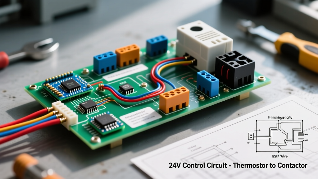
Installing a bypass humidifier requires more than just connecting wires to make the unit turn on; it demands strict adherence to electrical safety standards and mechanical codes. The wiring diagram for Aprilaire 600 outlines a 24-volt AC control circuit that interfaces directly with your HVAC system's blower and thermostat. In 2026, with the proliferation of power-hungry smart thermostats and advanced furnace control boards, understanding the electrical load limits and National Electrical Code (NEC) requirements for this system is critical.
Improper wiring of the Aprilaire 600 does not merely result in a non-functional unit. Bypassing the blower interlock can cause the water solenoid to open while the fan is off, dumping gallons of water into a stagnant duct system. This leads to catastrophic rust, microbial growth, and severe indoor air quality hazards. According to the EPA's guidelines on moisture control, unmanaged duct moisture is a primary catalyst for toxic mold proliferation in residential HVAC systems.
Critical Electrical Specifications & Component Limits
Before cutting any wire, verify that your components meet the exact specifications required for safe, code-compliant operation. The Aprilaire 600 relies on a low-voltage circuit, but the inrush current of the solenoid valve can easily overload undersized transformers.
| Component | Specification / Model | Electrical Rating | Safety & Code Notes |
|---|---|---|---|
| Solenoid Valve | Aprilaire 4040 | 24V AC, 0.5A Inrush | Requires minimum 20V at the valve to prevent chatter and overheating. |
| Transformer (Standard) | Aprilaire 50 | 120V to 24V AC, 40VA | Must be fused on the secondary side (3A slow-blow) per NEC 430. |
| Transformer (Smart Home) | Honeywell AT72D1683 | 120V to 24V AC, 75VA | Required in 2026 setups sharing a C-wire with Wi-Fi thermostats. |
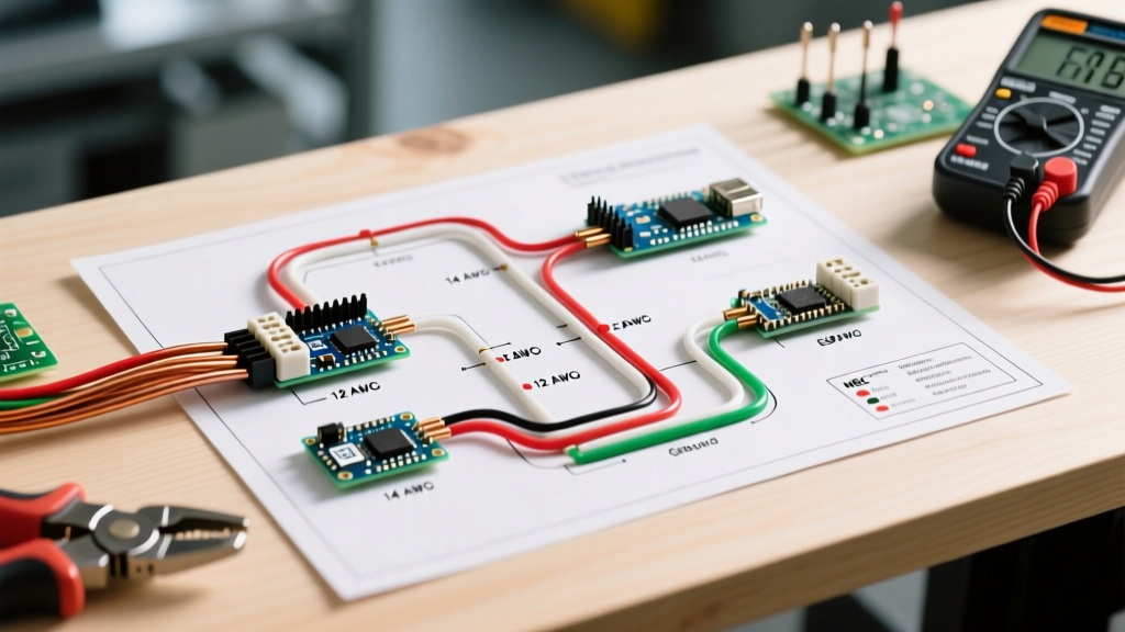
| Control Wire | 18 AWG Solid Copper | Class 2 (Max 30V) | Max run length 150 ft to prevent voltage drop below 20V. |
| Line Voltage Wire | 14 AWG or 12 AWG THHN | Class 1 (120V) | Must be routed in separate conduit/knockouts from Class 2 wiring. |
NEC Code Compliance: Class 1 vs. Class 2 Circuits
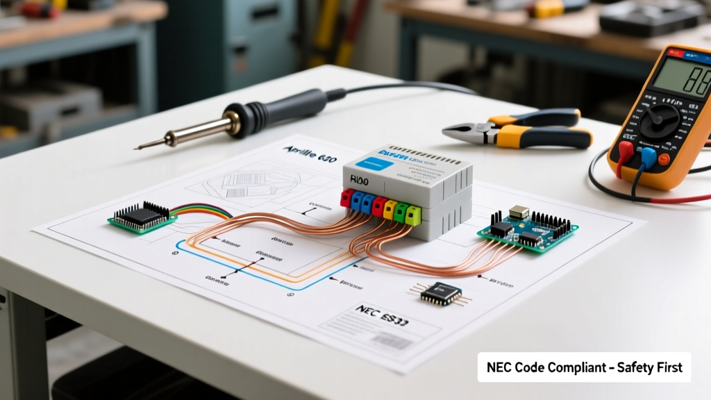
The most common code violation when wiring the Aprilaire 600 is mixing line voltage (120V) and low voltage (24V) in the same junction box without a physical barrier. Under NEC Article 725.136, Class 1 (power) and Class 2 (signaling/control) circuits must be separated by a minimum of 2 inches or divided by a grounded metal barrier.
Code Compliance Warning: Never run the 18 AWG thermostat wire through the same conduit or knockout hole as the 120V line feeding the furnace or the external transformer. A short circuit between 120V and 24V wiring will instantly destroy the furnace control board, the smart thermostat, and the humidifier solenoid, while posing a severe shock hazard.
Step-by-Step Wiring Sequence for Code Compliance
Follow this sequence to ensure your installation meets both the manufacturer's schematic and local electrical codes.
- Power Disconnect (NEC 110.25): Turn off the main breaker to the air handler/furnace. Verify zero voltage at the control board using a CAT III multimeter. Lockout/tagout the panel if working in a shared mechanical room.
- Transformer Mounting: If using an external 75VA transformer (highly recommended for modern smart thermostats), mount it to a standard 4x4 metal junction box. Do not leave the transformer 'floating' inside the ductwork or furnace cabinet.
- Humidistat Wiring: Run 18 AWG 2-conductor (or 4-conductor for digital stats) from the humidistat to the solenoid. Connect the humidistat 'H' (or 'W') terminal to one side of the solenoid, and the 'C' terminal to the transformer common.
- Solenoid Connection: Connect the remaining solenoid wire to the blower interlock source (detailed in the matrix below). Use wire nuts rated for 18 AWG solid copper, and wrap with electrical tape to prevent vibration-induced loosening.
- Water Line Grounding: While not strictly an electrical wiring step, NEC 250.52 requires metal water supply lines to be bonded to the building's grounding electrode system. Ensure the copper line feeding the Aprilaire saddle valve is properly grounded.
Blower Interlock Methods: Safety & Performance Matrix
The Aprilaire 600 must only receive power when the HVAC blower is actively moving air. The Department of Energy emphasizes that whole-house humidifiers must be interlocked with the fan to prevent duct saturation. Below is a comparison of the three approved interlock methods.
| Interlock Method | How It Works | Pros | Cons & Edge Cases |
|---|---|---|---|
| Furnace Board 'HUM' Terminal | Uses a dedicated 24V terminal on the furnace board that energizes only during a heat call. | Cleanest install; no extra relays; fully isolated. | Only runs during heating cycles. If you need humidity during fan-only or AC modes, this method fails. |
| Current Sensing Relay (CSR) | A split-core coil clamps around the 120V blower motor wire. When current flows, it closes a dry contact to send 24V to the solenoid. | Runs in Heat, Cool, and Fan-Only modes. Highly reliable. | Requires adjusting the amp-turn dial. Fails if the blower motor capacitor degrades and amp draw drops. |
| Sail Switch (Airflow Proving) | A physical paddle inserted into the duct closes a microswitch when air pressure pushes it. | Directly measures airflow, not just motor power. | Prone to mechanical failure from dust buildup. Requires cutting a hole in the main supply plenum. |
Real-World Failure Modes & Troubleshooting
Even with a perfect wiring diagram for Aprilaire 600, field conditions can introduce faults. Here is how to diagnose the most common safety and operational failures.
1. Solenoid Valve Chatter (Low Voltage Drop)
Symptom: The solenoid emits a loud, rapid buzzing sound and water trickles inconsistently. Root Cause: Voltage at the solenoid is dropping below 20V AC. This is almost always caused by using an undersized 40VA transformer that is simultaneously powering a Wi-Fi thermostat and the humidifier. Solution: Measure voltage at the solenoid with the circuit loaded. If it reads below 22V, upgrade to a 75VA transformer and ensure the 18 AWG wire run does not exceed 150 feet.
2. Transformer Burnout (Short Circuit)
Symptom: The transformer is hot to the touch, smells of burnt ozone, and outputs 0V. Root Cause: A short in the 18 AWG control wire, often caused by a staple piercing the insulation during installation, or water ingress into the solenoid housing. Solution: Disconnect the humidifier wires at the transformer. Use a multimeter to check continuity between the 'R' and 'C' wires. If resistance is near zero ohms, trace the wire for physical damage. Always install a 3A inline fuse on the secondary (24V) side of the transformer to protect it from future shorts.
3. Mold Growth in Supply Plenum
Symptom: Musty odors from supply registers; visible black spotting on duct liner. Root Cause: The blower interlock was wired to a constant 24V source, or the current sensing relay is stuck closed, allowing water to flow when the blower is off. Solution: Verify the interlock wiring. Ensure the humidistat and interlock relay are wired in series, not parallel. Both the humidistat call for humidity AND the blower proof of operation must be satisfied simultaneously for the solenoid to open.
Summary & Final Safety Checks
Wiring the Aprilaire 600 safely requires respecting the boundary between high-voltage power and low-voltage control signals. By upgrading to a 75VA transformer for modern smart-home compatibility, utilizing a current sensing relay for comprehensive blower interlock, and strictly following NEC Article 725 separation rules, you ensure a system that protects both your home's infrastructure and its indoor air quality. Always verify local mechanical codes regarding drain pan requirements and saddle valve prohibitions before finalizing your water line connections.