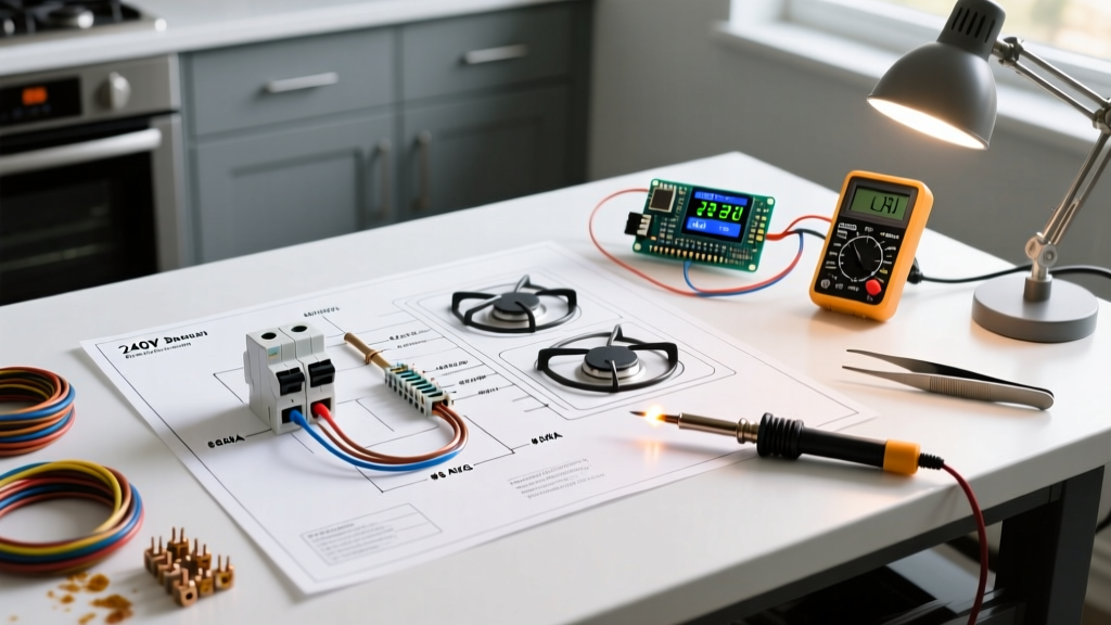

Decoding the Electric Stove Wiring Diagram
Upgrading to a modern freestanding range or a high-BTU induction cooktop requires more than just plugging in an appliance. It demands a rigorous understanding of the electric stove wiring diagram and the underlying 240V split-phase electrical system. Unlike standard 120V household circuits that utilize a single hot wire, an electric range requires two 120V hot legs (L1 and L2) out of phase with each other to deliver 240V for the heating elements, alongside a neutral wire for 120V accessories (like the oven light and digital clock), and a dedicated equipment grounding conductor.
Before pulling any wire through your walls, you must map out the circuit from the main service panel to the receptacle. According to the National Fire Protection Association (NFPA), Article 210.19 of the National Electrical Code (NEC) mandates specific branch circuit sizing for household cooking appliances. Misinterpreting the manufacturer's wiring schematic is the leading cause of tripped breakers, melted terminal blocks, and electrical fires in kitchen renovations.
Load Calculations and Breaker Sizing Matrix
The most critical step in your installation planning guide is matching the stove's kilowatt (kW) rating to the correct breaker and wire gauge. Modern electric stoves with convection ovens and induction zones frequently push the boundaries of traditional 40-amp circuits. Below is a sizing matrix based on standard residential 240V single-phase power.
| Stove kW Rating | Approx. Amp Draw (240V) | Required Breaker Size | Minimum Copper Wire Gauge | Receptacle Type |
|---|---|---|---|---|
| Up to 8.75 kW | 36.4 A | 40 Amp (2-Pole) | 8 AWG | NEMA 14-50 (50A rated) |
| 8.76 kW - 12.0 kW | 36.5 A - 50 A | 50 Amp (2-Pole) | 6 AWG | NEMA 14-50 |
| 12.1 kW - 15.0 kW | 50.4 A - 62.5 A | 60 Amp (2-Pole) | 4 AWG | Hardwired (Junction Box) |
The 40-Amp vs. 50-Amp Dilemma
Even if your specific electric stove wiring diagram calls for a 40-amp breaker, industry best practice in 2026 is to install a 50-amp circuit (using 6 AWG wire and a NEMA 14-50 receptacle). Why? Future-proofing. The U.S. Department of Energy notes that modern energy-efficient appliances are drawing more peak power during simultaneous multi-zone heating. Upgrading to 6 AWG wire now costs roughly $0.40 more per foot than 8 AWG but saves thousands in future rewiring if you upgrade to a commercial-style induction range later.
Wire Selection: NM-B Cable vs. THHN in Conduit
When planning your wire routing, you have two primary choices for residential branch circuits:
- 6/3 NM-B (Romex) with Ground: This non-metallic sheathed cable contains two insulated hot wires (Black, Red), one insulated neutral (White), and a bare copper ground. It is ideal for running through wooden wall studs and floor joists in dry, indoor locations. Cost: ~$2.10 per foot.
- 6 AWG THHN/THWN in EMT Conduit: If your route passes through masonry, exposed basement ceilings, or requires sharp bends, pulling individual THHN wires through 3/4-inch Electrical Metallic Tubing (EMT) is superior. It offers better heat dissipation and physical protection. Cost: ~$2.80 per foot (including conduit).
Voltage Drop Warning: If the distance from your main panel to the stove receptacle exceeds 75 feet, the NEC recommends upsizing your wire by one gauge (e.g., from 6 AWG to 4 AWG) to mitigate voltage drop, which can cause range control boards to malfunction and heating elements to underperform.
The 3-Prong vs. 4-Prong Transition (NEC 250.140)
One of the most dangerous edge cases in kitchen wiring involves older homes. Prior to 1996, the NEC allowed the neutral and ground to be bonded at the appliance via a 3-prong cord (NEMA 10-50). Today, NEC Article 250.140 strictly requires a separate equipment grounding conductor, meaning a 4-prong setup (NEMA 14-50).
Critical Terminal Block Configuration
When you look at the back of your new stove, you will see a terminal block with three or four screws. If you are connecting a modern 4-prong cord to the stove, you must remove the copper grounding strap that connects the center neutral terminal to the metal chassis of the stove.
- Disconnect the bonding strap or wire linking the neutral (center) terminal to the stove frame.
- Connect the Red wire to L1 (Left terminal).
- Connect the Black wire to L2 (Right terminal).
- Connect the White neutral wire to the center terminal.
- Connect the Green (or bare) ground wire directly to the metal chassis grounding screw.
Failure Mode: If you leave the bonding strap intact on a 4-prong system, normal neutral return current will flow through the equipment grounding wire, energizing the metal chassis of the stove and creating a severe shock hazard. The Consumer Product Safety Commission (CPSC) frequently cites improper appliance grounding as a leading cause of residential electrocution.
Step-by-Step Installation Planning Checklist
Use this checklist before cutting any drywall or purchasing materials:
- Panel Capacity Check: Verify your main service panel has at least two adjacent open slots and sufficient amperage headroom (a 50A range requires a 200A main service in most modern homes).
- Receptacle Height Planning: The NEMA 14-50 receptacle should be installed approximately 30 to 36 inches above the finished floor, centered behind the stove, but offset slightly to avoid interfering with the stove's rear anti-tip bracket.
- Torque Verification: Purchase an inch-pound torque screwdriver. Terminal block lugs on ranges typically require 20 to 25 in-lbs of torque. Hand-tightening leads to high-resistance connections that will arc and melt the block under a 40-amp load.
- Strain Relief Installation: Ensure the 4-prong power cord has a proper UL-listed strain relief clamp where it enters the stove's rear access panel to prevent the wires from pulling out of the terminal block.
Common Edge Cases and Troubleshooting
Aluminum Branch Wiring: Some homes built in the 1970s used aluminum wire. If you are tapping into existing aluminum wiring, you must use CO/ALR rated breakers and terminals, and apply antioxidant paste (like Noalox) to prevent galvanic corrosion. However, for a new 2026 installation, always pull new copper wire.
Shared Neutrals (Multi-Wire Branch Circuits): Never attempt to wire a 240V stove using two separate 120V circuits that share a neutral. The stove requires a dedicated, simultaneous-trip 2-pole breaker with a common internal trip mechanism or an approved handle tie to ensure both hot legs disconnect simultaneously during a fault.
Induction Range Noise: High-end induction ranges utilize high-frequency switching power supplies. If you notice interference with nearby Wi-Fi or audio equipment, ensure your circuit grounding path has low impedance and consider routing the NM-B cable at least 12 inches away from low-voltage data cables.
By thoroughly studying the electric stove wiring diagram and adhering to these planning parameters, you ensure a safe, code-compliant, and high-performance installation that will reliably power your kitchen for decades.