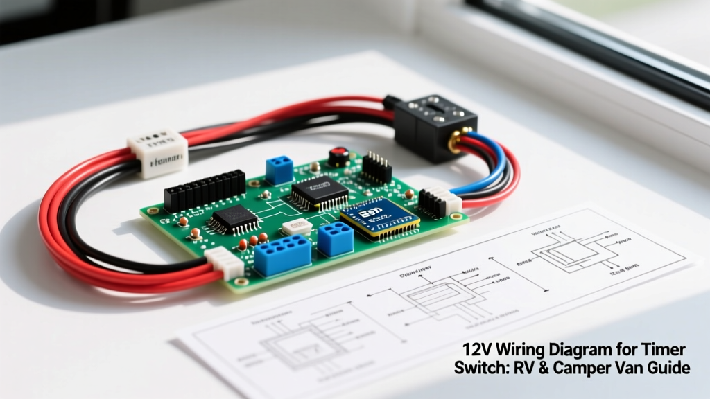

The Parasitic Drain Problem in Modern RVs and Camper Vans
As we navigate the 2026 landscape of off-grid vehicle builds, the widespread adoption of LiFePO4 (Lithium Iron Phosphate) battery banks in camper vans and Class B RVs has completely revolutionized boondocking. However, these advanced batteries feature internal Battery Management Systems (BMS) with strict low-voltage cutoffs. A forgotten interior light, a continuously running 12V ventilation fan, or an accidentally left-on water pump can trigger a deep discharge. When this happens, the BMS will permanently lock the battery to protect the cells from catastrophic damage. To prevent this, consulting a proper wiring diagram for timer switch configurations is no longer just a convenience—it is a critical safeguard for your DC electrical architecture.
In this comprehensive vehicle-specific guide, we break down the exact wiring methodology for integrating a 12V DC timer switch to control high-draw accessories. We will focus on a real-world scenario: wiring a timer to control a Shurflo 4008 Revolution 12V water pump and auxiliary ventilation fans, ensuring they automatically shut off after a preset duration to eliminate parasitic drain.
Core Components and 2026 Bill of Materials (BOM)
Automotive and marine environments demand components that can withstand heavy vibration, thermal cycling, and high-humidity conditions. Standard household AC timers will fail rapidly in a 12V DC vehicle environment. Below is the exact BOM required for a robust, relay-switched timer circuit.
| Component | Specific Model / Brand | Estimated Cost (2026) | Purpose |
|---|---|---|---|
| Digital Timer Module | DROK 12V-24V DC Digital Timer (Model 100114) | $16.50 | Provides adjustable countdown logic (1s to 99min) |
| Heavy-Duty Relay | Bosch 5-Pin 30A/40A 12V DC Relay (0332014150) | $7.25 | Handles high-current inductive loads safely |
| Primary Wire (Load) | Ancor Marine Grade 10 AWG TXL | $0.85 / ft | Carries main current to the water pump/fan |
| Control Wire | Ancor Marine Grade 14 AWG TXL | $0.55 / ft | Connects timer module to relay coil |
| Overcurrent Protection | Blue Sea Systems ATC Blade Fuse (15A) | $4.10 | Protects the load circuit from short circuits |
| Termination Tool | Knipex 97 53 14 Crimping Pliers | $115.00 | Ensures gas-tight crimps on heat-shrink terminals |
Total circuit cost (excluding tools): Approximately $35 - $45 depending on wire run length.
Visualizing the 12V Wiring Diagram for Timer Switch Logic
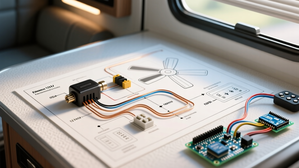
Because high-draw vehicle accessories like water pumps (which can pull up to 7.5A on startup and stall) or HVAC fans exceed the direct-switching capacity of most compact digital timer modules, we use the timer to trigger a heavy-duty Bosch automotive relay. This separates the low-current control logic from the high-current load path.
Timer Module Pinout (DROK 4-Wire DC)
- Red Wire (V+): Connects to a switched 12V ignition source or a dedicated DC breaker panel.
- Black Wire (V-): Connects to the vehicle's main DC negative busbar.
- White Wire (Trigger/IN): Connects to a momentary push-button switch. Pressing this button starts the timer countdown.
- Blue Wire (Output/OUT): Outputs +12V only while the timer is actively counting down. Connects to Relay Pin 85.
Bosch 5-Pin Relay Pinout (ISO Mini)
- Pin 86 (Coil +): Connects to +12V fused source.
- Pin 85 (Coil -): Connects to the Timer Blue Output wire. (When the timer is active, it grounds the coil through its internal transistor, energizing the relay).
- Pin 30 (Common Input): Connects to the main battery bank via a 15A ATC fuse.
- Pin 87 (Normally Open Output): Connects to the positive terminal of the water pump or fan.
- Pin 87a (Normally Closed): Capped and unused in this specific timer application.
Step-by-Step Installation and Termination Guide
According to the Victron Energy Wiring Unlimited guidelines, poor terminations are the leading cause of DC electrical fires in mobile applications. Follow these steps meticulously:
- Disconnect the Battery: Always isolate the main positive terminal of your LiFePO4 bank before cutting or stripping any wires.
- Install Overcurrent Protection: NFPA 1192 (Standard on Recreational Vehicles) mandates that overcurrent protection must be installed within 18 inches of the power source. Install your 15A ATC fuse holder on the 10 AWG red wire directly at the positive busbar.
- Route and Crimp the Load Circuit: Strip 3/8 inch of insulation from the 10 AWG wire. Use a heat-shrink ring terminal and the Knipex crimping tool to create a gas-tight seal. Apply heat to shrink the insulation sleeve. Connect Pin 30 of the relay to the fused power, and Pin 87 to the water pump positive.
- Wire the Control Logic: Use 14 AWG wire for the timer module. Connect the timer's Red wire to a switched 12V source (so the timer itself doesn't draw standby current when the RV is in storage). Connect the Black wire to the negative busbar.
- Ground the Load: Route the water pump's negative wire back to the main DC negative busbar. Never use the vehicle's metal chassis as a ground return path in modern composite or aluminum-framed camper builds; always run a dedicated ground wire.
Load Comparison Matrix: Direct Timer vs. Relay-Switched
Why go through the trouble of adding a Bosch relay? The table below illustrates the danger of wiring high-inductive loads directly to a solid-state timer module.
| Accessory Type | Running Amps | Startup / Stall Amps | Direct Timer Safe? | Relay Required? |
|---|---|---|---|---|
| LED Interior Puck Lights | 0.5A | 0.5A | Yes (Up to 2A limit) | No |
| 12V USB Charging Ports | 1.2A | 1.5A | Yes | No |
| MaxxAir Roof Vent Fan | 1.8A | 3.5A | Borderline | Recommended |
| Shurflo 4008 Water Pump | 6.0A | 7.5A - 10A | NO | Yes (Mandatory) |
| 12V Diesel Heater Glow Plug | 8.0A | 12.0A+ | NO | Yes (Mandatory) |
Expert Insight: Inductive loads like DC motors generate a massive back-EMF (electromotive force) voltage spike when switched off. If wired directly to a cheap digital timer, this spike will instantly fry the timer's internal MOSFET. The Bosch relay's physical contacts safely absorb and extinguish this arc, protecting your low-voltage control logic.
Calculating Voltage Drop for the Control Circuit
A common failure mode in camper van timer installations is the timer module resetting randomly or failing to trigger the relay. This is almost always caused by voltage drop on the 14 AWG control wires. If the voltage at the timer's input drops below 10.5V, the microcontroller will brown-out and reset the countdown.
Using the standard DC voltage drop formula, a 15-foot run of 14 AWG copper wire carrying 0.2A (the timer's internal draw) results in a voltage drop of only 0.015V, which is negligible. However, if you mistakenly use 18 AWG wire and run it 30 feet through a conduit with high ambient heat, the resistance increases, and the voltage at the relay coil (Pin 85) may drop below the 9V threshold required to pull the relay's internal spring. Always stick to 14 AWG minimum for control runs exceeding 10 feet in a vehicle.
Troubleshooting Edge Cases in LiFePO4 Systems
Modern RV electrical systems present unique edge cases that older wiring diagrams fail to address. Here are three specific failure modes and their solutions:
1. The 'Ghost Trigger' from Alternator Spikes
When the vehicle's alternator kicks in, it can send transient voltage spikes up to 14.8V or higher through the chassis wiring. If your timer module lacks internal opto-isolation, these spikes can trick the microcontroller into starting a countdown. Solution: Install a 12V Zener diode or a transient voltage suppression (TVS) diode across the timer's power input terminals to clamp voltage spikes.
2. BMS Low-Voltage Cutoff Conflict
If your LiFePO4 battery drops to 11.8V, the BMS may disconnect the load. When the timer attempts to trigger the relay, the sudden inrush current of the relay coil (approx. 150mA for a fraction of a second) can cause a momentary voltage sag, tricking the BMS into thinking a short circuit has occurred. Solution: Ensure your timer is wired to a dedicated 'house' battery bank with a robust BMS (like a Victron Smart BMS) rather than a budget drop-in battery with undersized internal FETs.
3. Corrosion on the Relay Socket
Camper vans experience extreme humidity swings. Standard automotive relay sockets use tin-plated brass, which oxidizes rapidly in coastal or high-humidity environments, increasing resistance and causing the relay to chatter. Solution: Use a marine-grade relay socket with nickel-plated contacts, and apply a dab of dielectric grease (like NO-OX-ID) to the pins before seating the Bosch relay.
Authoritative Standards and References
When designing or modifying any 12V DC system in a recreational vehicle, adherence to established safety standards is non-negotiable. The wiring methodologies detailed in this guide comply with the core tenets of the following frameworks:
- NFPA 1192 (Standard on Recreational Vehicles): Dictates the placement of overcurrent protection and wire sizing requirements for 12V DC systems in RVs. You can review the scope of these standards via the National Fire Protection Association.
- ABYC E-11 (AC & DC Electrical Systems on Boats): While technically a marine standard, the American Boat & Yacht Council E-11 standard is widely considered the gold standard for 12V DC wire sizing, derating for engine space heat, and vibration resistance in mobile environments.
- Victron Energy Wiring Unlimited: An industry-leading open-source reference manual for DC architecture, detailing busbar sizing, grounding topologies, and lithium battery integration.
By following this precise wiring diagram for timer switch integration, you ensure that your camper van or RV remains safe, efficient, and protected against the silent threat of parasitic battery drain.