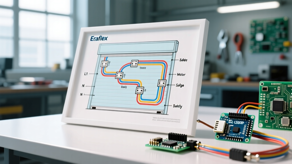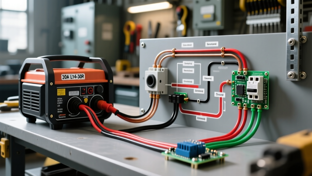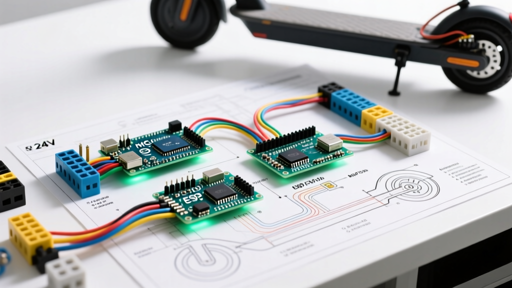

The Anatomy of a Compliant 24 Volt Electric Scooter Wiring Diagram
Building or repairing a custom electric scooter requires more than just connecting red to positive and black to negative. A properly engineered 24 volt electric scooter wiring diagram must prioritize safety, thermal management, and overcurrent protection. As micromobility devices face increased scrutiny from safety regulators in 2026, adhering to electrical codes and battery safety standards is no longer optional—it is critical for preventing thermal runaway and electrical fires.
A standard 24V scooter system typically draws between 15A and 35A continuously, with peak surge currents exceeding 50A during acceleration or hill climbs. At these current levels, undersized wires and poor crimp connections will generate enough resistive heat to melt insulation and ignite surrounding plastics. This guide breaks down the exact wiring topology, wire gauge mathematics, and safety compliance requirements for 24V DC scooter platforms.
Core Components and Signal Flow
Before routing any wires, you must understand the logical flow of both the high-current power loop and the low-voltage signal loop. A safe 24V system isolates these two circuits to prevent high-voltage feedback from frying sensitive Hall-effect sensors.
- Power Source: Two 12V 12Ah Sealed Lead Acid (SLA) batteries in series, or a single 24V (7S or 8S) LiFePO4/Li-ion pack with an integrated Battery Management System (BMS).
- Main Disconnect/Breaker: A 24V DC-rated magnetic circuit breaker (e.g., 40A or 50A) mounted within 6 inches of the battery positive terminal.
- Speed Controller: A 24V brushed or brushless motor controller (typically rated for 350W to 500W). Ensure it features low-voltage cutoff (LVC) and overcurrent protection.
- Throttle & Brake Inhibits: 3-wire Hall-effect throttle (5V signal) and normally-open (NO) brake levers that cut the motor signal instantly upon engagement.
- Drive Motor: 24V DC hub motor or chain-driven transmission motor.
Wire Gauge Selection and Voltage Drop Mitigation
The most common failure mode in DIY scooter builds is voltage drop caused by undersized wiring. In a 24V DC system, a 3% voltage drop equates to a loss of 0.72V. While this seems minor, the resistive heat generated in the wire (I²R losses) is the real danger. According to principles adapted from the National Electrical Code (NEC NFPA 70), conductors must be sized to handle 125% of the continuous load without exceeding their temperature rating.
24V DC Wire Sizing Matrix (Copper, 75°C Rating)
| Continuous Current | Peak Surge | Recommended AWG | Max Length (Round Trip) | Typical Application |
|---|---|---|---|---|
| 10A - 15A | 20A | 14 AWG | 8 feet | Lighting, Horn, DC-DC Converters |
| 15A - 20A | 30A | 12 AWG | 10 feet | 250W Motor Power Loop |
| 20A - 30A | 45A | 10 AWG | 12 feet | 350W - 500W Motor Power Loop |
| 30A - 40A | 60A | 8 AWG | 14 feet | High-Performance 600W+ Builds |
Note: Always use stranded, silicone-insulated wire for scooter builds. PVC insulation becomes brittle under the constant vibration of a scooter deck and can crack, leading to short circuits against the metal chassis.
Overcurrent Protection and Code Compliance
Fuses and breakers are your last line of defense against a dead short. In 24V DC systems, standard automotive AC/DC fuses can suffer from sustained DC arcing, which prevents the fuse element from clearing the fault. You must use DC-specific or high-interrupting-capacity fuses.
Fuse and Breaker Selection Guide
- Main Battery Fuse (ANL or Class T): Use a 50A ANL fuse or a Class T fuse (like the Blue Sea Systems 5502) on the main positive trunk. Class T fuses have an interrupting capacity of 20,000 Amps, crucial for lithium battery packs that can dump massive short-circuit currents.
- Branch Circuit Fuses (ATC/ATO): For low-current accessories (lights, USB chargers), use standard blade fuses sized at 125% of the accessory draw. A 5A lighting circuit should use a 7.5A ATC fuse.
- Circuit Breakers: If using a breaker as a main disconnect, ensure it is explicitly rated for DC voltage. A 40A DC breaker from Bussmann or Blue Sea is ideal. Never use AC-only household breakers for DC scooter applications.
Safety Warning: As of 2026, the U.S. Consumer Product Safety Commission (CPSC) has heavily penalized the use of non-compliant, uncertified battery packs in micromobility devices. Always ensure your 24V lithium battery pack carries a valid UL 2271 certification for Light Electric Vehicles.
Step-by-Step Safe Wiring Procedure
Follow this sequence to ensure a logical, safe, and easily troubleshootable build.
Phase 1: The High-Current Power Loop
- Isolate the Battery: Ensure the main battery switch is OFF and the negative terminal is physically disconnected.
- Install the Main Fuse: Crimp a ring terminal onto your 8 AWG or 10 AWG red wire. Attach it to the positive battery terminal, routing it immediately to the input side of your ANL fuse holder.
- Route to Controller: Run the fused positive wire to the main power input (B+) on the speed controller. Keep this wire as short and direct as possible.
- Complete the Ground: Run the black (negative) wire from the battery negative terminal (B-) directly to the controller's main ground (B-). Never route the main motor ground through the scooter's metal frame; always use a dedicated copper return wire.
Phase 2: The Low-Voltage Signal Loop
- Throttle Connection: Connect the 3-pin throttle plug (usually Red=5V, Black=Ground, Green/White=Signal). Use heat shrink and solder; do not rely solely on crimp pins for the throttle signal, as vibration causes intermittent signal loss, leading to runaway acceleration.
- Brake Inhibits: Wire the brake levers to the controller's E-ABS or brake inhibit pins. Test this with the rear wheel elevated before riding. If the motor does not cut instantly when the lever is pulled, reverse the polarity or check the NO/NC jumper on the controller.
- Ignition Switch: Wire a heavy-duty toggle switch or key switch in line with the controller's 'Ignition' or 'Lock' wire (usually a thin red or orange wire). This wakes up the controller's logic board without passing the main 30A motor current through the delicate key switch.
Common Failure Modes and Edge Cases
Even with a perfect diagram, physical execution errors cause most scooter fires. Watch out for these specific edge cases:
- Anderson Powerpole Melting: The Anderson SB50 connector is rated for 50A, but only if you use the correct AWG wire and the official Anderson crimp die (or a high-quality equivalent like the IWISS SN-28B). A poorly crimped SB50 will develop high resistance and melt at 30A.
- Chafing on the Swingarm: The motor phase wires pass through the hollow axle and swingarm. If the axle nut pinches the wire insulation against the sharp inner edge of the swingarm, the frame becomes electrified. Always use a rubber grommet and wrap phase wires in braided fiberglass sleeving.
- BMS Bottleneck: If your 24V Li-ion pack has a cheap 20A BMS, but your controller pulls 30A on hills, the BMS will cut power abruptly. This sudden loss of power at high speed can cause a crash. Ensure your BMS continuous discharge rating exceeds your controller's maximum current limit by at least 20%.
Frequently Asked Questions (FAQ)
Can I use a 12V automotive relay for my 24V scooter headlights?
No. While a 12V relay coil might pull in at 24V, it will overheat and fail rapidly. Furthermore, the internal arc suppression diode will be reverse-biased incorrectly if wired backward. Always use relays explicitly rated for 24V DC coils and contacts.
Do I need to ground the metal frame of the scooter to the battery negative?
In standard automotive (12V) systems, chassis grounding is common. However, in 24V and higher DC scooter builds, it is best practice to run dedicated negative return wires for all components. Relying on the aluminum or steel frame for ground return introduces unpredictable resistance and can cause stray currents that interfere with the controller's logic board.
What is the safest connector for the battery-to-controller joint?
For currents under 60A, the XT90-SAnderson SB50 are the industry standards. The anti-spark feature in the XT90-S is highly recommended for lithium builds, as it prevents the massive inrush current from sparking and damaging the controller's capacitors upon connection.