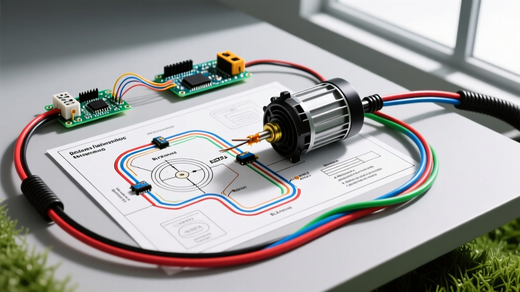

Understanding the Electric Lawn Mower Wiring Diagram
When diagnosing a dead motor, a tripped breaker, or an intermittent safety switch, consulting an accurate electric lawn mower wiring diagram is the difference between a $15 component fix and a $300 total replacement. As of 2026, the residential market is heavily split between legacy 120V corded universal motors and advanced 40V to 80V brushless DC (BLDC) cordless platforms. Each topology requires a radically different diagnostic approach, specific multimeter settings, and distinct safety protocols.
This reference guide breaks down the exact schematic pathways, component node values, and failure modes for both architectures. Whether you are repairing a 13-amp corded Black+Decker MM20 or troubleshooting the Electronic Speed Controller (ESC) on a Ryobi 40V brushless model, understanding the underlying circuit logic is mandatory for safe and effective repair.
Corded Electric Mower Schematic: Universal Motor Architecture
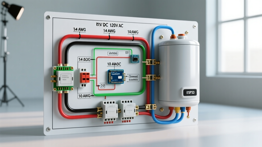
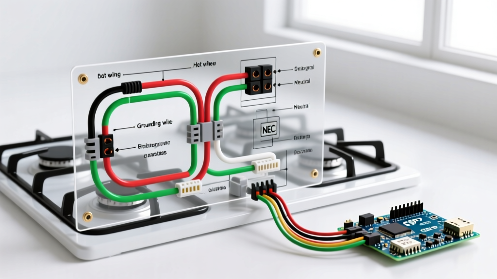
The typical 120V AC corded mower relies on a series-wound universal motor. The wiring diagram for this system is deceptively simple but contains critical safety interlocks designed to handle high inductive loads. The current path generally flows from the Hot wire (black) through a Double-Pole Single-Throw (DPST) safety bail switch, into a thermal overload protector, through the stator windings, across the carbon brushes to the rotor commutator, and finally out through the Neutral wire (white).
Critical Components and Failure Modes
- Safety Bail Switch (DPST): Unlike simple SPST switches, a DPST switch breaks both the hot and neutral lines simultaneously. This prevents the motor from energizing if a neutral fault occurs upstream. Failure usually manifests as contact pitting due to the 13A inductive inrush current.
- Thermal Overload Protector: Typically a Texas Instruments 17AM series bimetallic disc rated for a 125°C trip point. It sits directly against the stator windings. If the mower is used in thick, wet grass, current spikes cause the bimetallic strip to heat, warp, and break the circuit. Over years of use, the metal fatigues, causing premature tripping even under normal loads.
- Carbon Brushes: These transfer AC current to the spinning rotor. They must maintain a minimum length of 1/4 inch. Worn brushes cause arcing at the commutator, leading to visible blue sparks and eventual commutator scoring.
Corded Mower Multimeter Troubleshooting Matrix
| Component Node | Multimeter Setting | Expected Reading | Common Failure Mode | Est. Repair Cost |
|---|---|---|---|---|
| Power Cord (14 AWG SJTW) | Continuity | < 1.0 Ohm | Internal copper fracture near strain relief | $18 - $25 |
| Safety Bail Switch | Continuity | 0.0 Ohm (Closed) | Contact pitting from 13A inductive load | $12 - $22 |
| Thermal Overload (17AM) | Continuity | 0.0 Ohm (Cold) | Fatigued bimetallic strip (trips prematurely) | $6 - $10 |
| Carbon Brushes (Pair) | Resistance | 2.0 - 5.0 Ohms | Worn past 1/4 inch, spring tension loss | $8 - $14 |
Cordless Brushless DC (BLDC) Mower Wiring: ESC and Phase Mapping
Modern cordless mowers eliminate carbon brushes and commutators, replacing them with an Electronic Speed Controller (ESC) and a 3-phase BLDC motor. The electric lawn mower wiring diagram for these units is essentially a high-current DC power distribution network paired with low-voltage logic signaling. According to the U.S. Department of Energy Motor Systems division, BLDC architectures offer up to 30% higher efficiency and significantly longer lifespans than brushed counterparts, but their solid-state components introduce complex diagnostic challenges.
The ESC and 3-Phase Power Delivery
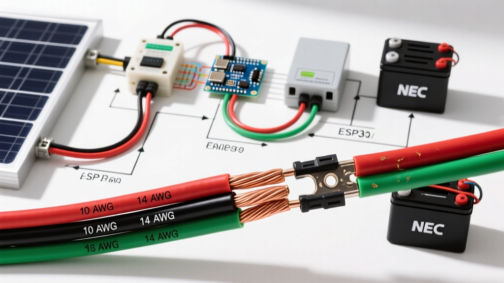
The battery (ranging from 40V to 80V nominal) connects to the main control board via heavy-gauge silicone wiring (usually 12 AWG or 10 AWG). The ESC utilizes a 3-phase bridge of N-channel MOSFETs to commutate the DC battery voltage into simulated AC waveforms for the motor's U, V, and W phase wires. If your mower clicks once but the blade refuses to spin, the ESC has likely detected a phase fault or a blown MOSFET. Testing the MOSFET bridge requires a diode-test setting on your multimeter; a reading of 0.00V across the drain and source indicates a shorted (blown) FET, requiring a complete ESC replacement ($45 to $85).
Hall Effect Sensor Pinout Reference
The ESC relies on three Hall effect sensors embedded in the motor stator to determine rotor position. These are routed back to the ESC via a 5-pin JST connector. When diagnosing a stuttering or cogging motor, verify the pinout voltages while the battery is connected and the trigger is pulled:
- Pin 1 (VCC): Should read exactly 5.0V DC (supplied by the ESC logic regulator).
- Pin 2 (Ground): 0.0V DC reference.
- Pin 3 (Hall A): Pulses between 0V and 5V as the rotor spins.
- Pin 4 (Hall B): Pulses between 0V and 5V, offset 120 electrical degrees from A.
- Pin 5 (Hall C): Pulses between 0V and 5V, offset 240 electrical degrees from A.
Expert Diagnostic Tip: If Pins 3, 4, or 5 remain stuck at 0V or 5V while the motor is manually rotated, a Hall sensor has failed or the internal wiring harness has chafed against the rotor. Do not attempt to solder new sensors into a sealed mower hub; replace the entire stator assembly to maintain the IP54 weatherproofing.
Safety Standards and Wire Gauge Selection
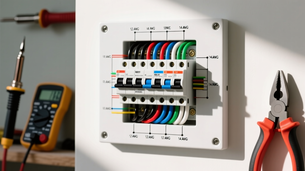
When replacing damaged wiring on any outdoor power equipment, strict adherence to gauge and insulation standards is non-negotiable. For 120V corded mowers drawing up to 15 amps, the replacement cord must be a minimum of 14 AWG, though 12 AWG is highly recommended to mitigate voltage drop over 100-foot extension runs. The NFPA 70 National Electrical Code (NEC) dictates that continuous loads should not exceed 80% of the conductor's ampacity. Furthermore, the jacket must be rated SJTW (Service, Junior, Thermoplastic, Water-resistant) to withstand UV degradation and moisture.
Regarding operational safety, OSHA Standard 1910.243 governing portable powered tools strictly prohibits the bypassing of safety interlocks. Bypassing a DPST bail switch by wire-nutting the hot and neutral lines directly to the motor not only violates federal safety guidelines but removes the critical secondary disconnect, creating a severe electrocution hazard if the mower housing becomes energized during a wet-grass mowing session.
Frequently Asked Questions (FAQ)
Why does my corded mower shut off after exactly 10 minutes of use?
This is the classic symptom of a fatigued thermal overload protector. The bimetallic disc inside the 17AM sensor has lost its structural tension over years of thermal cycling. It now trips at 85°C instead of its factory-rated 125°C. You can confirm this by testing the overload for continuity immediately after it shuts off; if it reads open (OL) and requires 15 minutes to cool down and reset, replace the $8 sensor rather than the entire motor.
Can I use a standard indoor 16 AWG extension cord for a 13-amp electric mower?
No. A 16 AWG cord is rated for a maximum of 10 amps. Running a 13-amp universal motor through a 16 AWG cord will cause the copper to heat up, melting the insulation and creating a severe fire hazard. Furthermore, the voltage drop across a 50-foot 16 AWG cord will starve the mower motor of voltage, causing it to draw excess amperage to compensate for the lost wattage, which will eventually burn out the stator windings.
My BLDC cordless mower clicks loudly but the blade won't spin. What is failing?
The single loud click is the main battery contactor engaging, followed immediately by the ESC aborting the startup sequence. This usually points to a phase wire short (where the U, V, or W silicone wires have melted together inside the deck) or a seized rotor bearing. Disconnect the 3-phase plug from the ESC and test the resistance between U-V, V-W, and U-W. All three readings should be identical (typically between 0.2 and 0.8 Ohms). If one pair reads OL or significantly higher, the motor stator is burnt out.