
Navigating the Double Wide Mobile Home Electrical Wiring Diagram
Wiring a double wide manufactured home requires navigating the strict intersection of the National Electrical Code (NEC) Article 550 and the federal HUD Code (24 CFR Part 3280). Unlike site-built homes, a double wide mobile home electrical wiring diagram must account for the physical split of the structure, requiring a specialized crossover junction at the marriage wall. As of the 2026 building cycle, inspectors are heavily scrutinizing ground/neutral isolation and AFCI compliance in manufactured housing.
This step-by-step walkthrough breaks down the exact architecture, materials, and execution required to safely wire a 200-amp double wide mobile home, ensuring compliance and long-term reliability.
Core Architecture: How the Diagram is Split
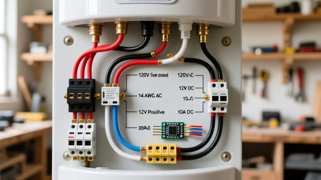
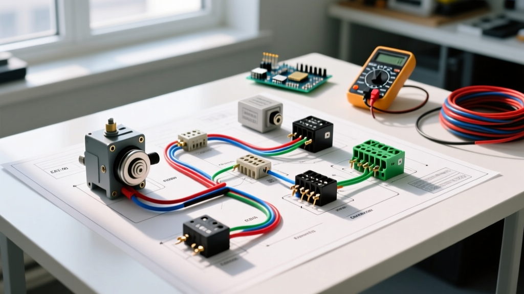
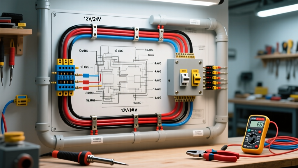
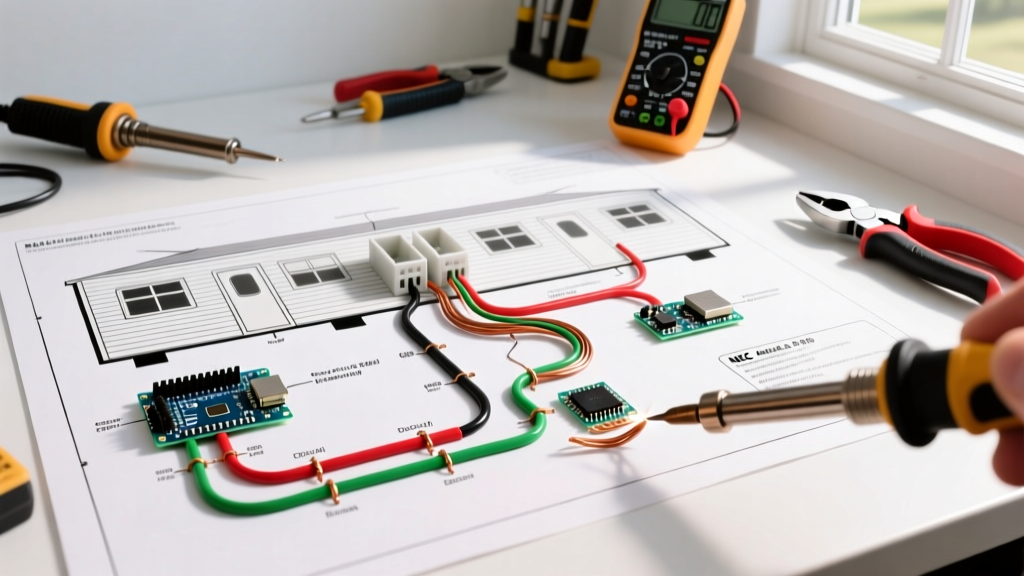
The fundamental challenge of a double wide is that the home is built in two separate chassis sections. The electrical system must bridge this gap safely. The standard diagram utilizes a single 200A main service panel located in one half (typically the utility room or master closet), which feeds branch circuits locally and routes a dedicated sub-feeder through the underbelly to a crossover junction box at the marriage wall. From this junction, the circuits distribute into the second half of the home.
Essential Materials & Wire Sizing Matrix
| Application | Wire Type & Gauge | Ampacity | Torque Spec |
|---|---|---|---|
| Service Entrance Feeder | 4/0-4/0-4/0-2/0 AL SER Cable | 200A | 250 in-lbs (Lugs) |
| Crossover Sub-Feeder | 2/0-2/0-2/0-1/0 AL SER or THHN | 125A - 150A | 180 in-lbs |
| 20A Branch Circuits | 12 AWG Copper NM-B (Romex) | 20A | N/A (Wire nuts) |
| Grounding Electrode | 6 AWG Bare Copper | N/A | 120 in-lbs (Acorn) |
Step 1: Service Entrance and Main Panel Installation
The service entrance begins at the weatherhead and meter base. For a 200A service, we recommend the Milbank U5652-XL ring-type meter socket, which provides ample gutter space for the large 4/0 AL SER cables.
- Mount the Main Panel: Install a 200A main breaker panel (e.g., Square D HOM200M200PC) in the designated utility space of the first half. Ensure the panel is mounted at least 48 inches above the finished floor to meet NEC working space requirements.
- Bonding the Neutral: In this main service panel, the neutral bus bar must be bonded to the ground bus bar and the panel chassis. This is the only location in the entire double wide where neutral and ground should be bonded.
- Grounding Electrode System: Drive two 8-foot copper-clad steel ground rods into the earth, spaced at least 6 feet apart. Connect them to the panel's ground bus using a continuous run of 6 AWG bare copper wire, secured with brass acorn clamps torqued to 120 in-lbs.
Step 2: Routing the Feeder to the Crossover Junction
The crossover feeder is the lifeline connecting the two halves of the home. Because it runs beneath the chassis, it is exposed to moisture, road debris (during transport), and rodents.
- Conduit Requirements: NEC Article 550 mandates that wiring exposed under the chassis must be protected. Run the 2/0 AL crossover feeder through 2-inch Liquidtight Flexible Metal Conduit (LFMC) or Schedule 80 PVC.
- Strapping and Support: Secure the conduit to the steel I-beam chassis using heavy-duty metallic straps every 3 feet. Never use plastic zip-ties for primary support, as they degrade under UV exposure and temperature fluctuations.
- Drip Loops: Before the conduit enters the marriage wall junction box, create a physical drip loop to prevent condensation from tracking directly into the electrical connections.
Step 3: The Crossover Connection (The Marriage Wall)
This is the most critical failure point in any double wide mobile home electrical wiring diagram. When the two halves of the home are pushed together on-site, the crossover junction must be mated securely.
Expert Warning: Never use standard wire nuts or push-in connectors for 2/0 AL crossover feeders. The thermal expansion and vibration of a mobile home will cause these to loosen, resulting in arcing and catastrophic fires.
The Proper Execution:
- Mount a Hoffman A202010CH NEMA 3R steel junction box precisely on the marriage wall rim joist of the first section.
- Terminate the incoming 2/0 AL feeder and the outgoing 2/0 AL branch feeds using Polaris IT-400 insulated multi-tap connectors. These blocks are specifically designed for aluminum wire, pre-filled with oxide-inhibiting compound to prevent galvanic corrosion.
- Torque the Polaris set-screws to exactly 180 in-lbs using a calibrated torque screwdriver. Under-torquing causes high-resistance hot spots; over-torquing strips the aluminum strands.
- Once the home sections are joined, seal the junction box perimeter with butyl tape and a silicone bead to prevent humid air from infiltrating the marriage wall cavity.
Step 4: Branch Circuit Wiring & 2026 AFCI/GFCI Rules
From the main panel and the crossover junction box, 12 AWG and 14 AWG NM-B cables distribute power to receptacles, lighting, and appliances. Modern HUD code and NEC adoptions require stringent fault protection.
Mandatory Protection Zones (2026 Standards)
- AFCI (Arc-Fault Circuit Interrupters): Required on all 15A and 20A branch circuits supplying living rooms, bedrooms, dining rooms, and closets. Use combination-type AFCI breakers (e.g., Square D HOM120CAFIC) to detect both parallel and series arcs.
- GFCI (Ground-Fault Circuit Interrupters): Mandatory for kitchens, bathrooms, garages, exterior receptacles, and any outlet within 6 feet of a wet bar or laundry sink. For kitchens, GFCI receptacles are preferred over GFCI breakers to prevent nuisance tripping of the entire kitchen circuit when a microwave faults.
Common Failure Modes & Troubleshooting
When troubleshooting an existing double wide, electricians frequently encounter specific issues born from improper diagram execution or settling of the chassis over time.
| Symptom | Root Cause | Diagnostic & Fix |
|---|---|---|
| Lights brighten/dim when appliances cycle | Loose neutral at the crossover junction or main service lug. | Check voltage at outlets. If one leg reads 130V and the other 110V, immediately kill power and re-torque all neutral lugs and Polaris blocks. |
| Subtle shock from appliance chassis | Improper neutral/ground bond in a downstream sub-panel. | Verify that the green bonding screw is removed in any secondary sub-panels. Ground and neutral must remain strictly isolated past the main service disconnect. |
| Repeated AFCI breaker tripping | Pierced NM-B cable under the chassis or at the marriage wall. | Inspect the underbelly where cables pass through steel studs. Ensure plastic grommets are installed in all metal knockouts to prevent insulation degradation. |
Authoritative References & Code Compliance
Executing a safe double wide mobile home electrical wiring diagram requires adherence to federal and national standards. Always consult the latest editions of the following codes before beginning work:
- National Fire Protection Association (NFPA): Refer to NFPA 70 (National Electrical Code), specifically Article 550, which dictates the exact grounding, panel, and feeder requirements for mobile and manufactured homes.
- U.S. Department of Housing and Urban Development (HUD): The HUD Code (24 CFR Part 3280, Subpart I) governs the factory-installed electrical systems and crossover junction standards that must be maintained during on-site assembly.
- U.S. Department of Energy (DOE): For insights on energy-efficient electrical layouts and HVAC integration in manufactured housing, review the DOE Manufactured Housing guidelines.
Frequently Asked Questions
Can I use copper wire for the crossover feeder instead of aluminum?
Yes, you can use 2/0 AWG Copper THHN/THWN-2 in conduit for the crossover feeder. However, aluminum (specifically AA-8000 series alloy) is the industry standard for mobile home feeders due to cost and weight. If you transition from AL to CU, you must use AL9CU-rated lugs and apply antioxidant paste to the aluminum terminations.
Does the second half of the double wide need its own sub-panel?
Not necessarily. The most common and cost-effective diagram uses a single 200A main panel with feed-through lugs that send a sub-feeder to a crossover junction box. The branch circuit breakers for the second half are physically located in the main panel, eliminating the need for a secondary sub-panel and keeping all overcurrent protection in one centralized location.