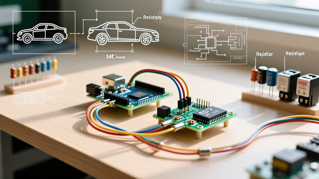

The Blueprint: Decoding Automotive Electrical Wiring Diagram Symbols
Planning a custom auxiliary light bar, high-amperage winch, or aftermarket audio system requires more than just connecting wires. Misinterpreting a single automotive electrical wiring diagram symbol can lead to a melted harness, a drained battery, or catastrophic ECU failure. Modern vehicles, especially those with complex CAN-bus architectures, demand precise installation planning. This guide breaks down standard SAE and DIN symbols, wire gauge specifications, and critical edge cases to ensure your 2026 automotive electrical projects are safe, reliable, and compliant.
Core SAE and DIN Symbol Matrix
Automotive schematics primarily rely on two standards: the US-based SAE (Society of Automotive Engineers) and the European DIN/ISO standards. While many symbols overlap, recognizing the nuances is vital for planning your harness routing and grounding points.
| Component | Diagram Symbol / Tag | Standard | Installation Planning Application |
|---|---|---|---|
| Chassis Ground | Inverted triangle with 3 descending horizontal lines | SAE / DIN | Indicates a direct connection to the vehicle frame. Plan to use a star washer and sand away paint to bare metal for a true zero-ohm ground. |
| Signal / Logic Ground | Standard ground symbol enclosed in an open circle | DIN / ISO | Used for low-voltage ECU sensors. Never tie high-amperage accessory grounds to these nodes; it will induce voltage spikes and trigger ECU faults. |
| SPST Relay (Normally Open) | Rectangle with coil symbol and a single switch line | SAE | Standard 4-pin Bosch-style relay. Plan for 30A continuous draw. Use 10 AWG wire for pins 30 and 87. |
| SPDT Relay | Rectangle with coil and two switch lines (NO and NC) | SAE / DIN | 5-pin relay (includes pin 87a). Crucial for winch solenoids or reversing polarity circuits. Requires careful thermal management. |
| Fusible Link | Rectangle with a diagonal line or a specific loop symbol | SAE | Often found near the battery positive terminal. Do not bypass. If upgrading an alternator, replace the factory fusible link with a high-amp ANL fuse block. |
| Splice / Junction | Solid black dot where two lines intersect | SAE / DIN | Indicates a factory harness splice. If tapping into this, use a T-tap only for temporary diagnostics; for permanent installs, cut, solder, and heat-shrink. |
Wire Gauge Standards: SAE J1128 vs. ISO 6722
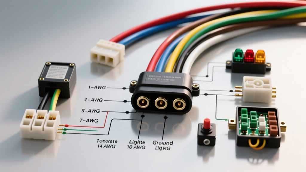
Automotive electrical wiring diagram symbols often include text tags next to the wire lines (e.g., "0.5 RD" or "18 BK") to denote cross-sectional area and color. Understanding these tags is critical for calculating voltage drop and selecting the right crimp terminals.
In North America, wire sizing typically follows SAE J1128 (Low Tension Primary Cable) using American Wire Gauge (AWG). In Europe and many modern global platforms, ISO 6722-1 uses metric cross-sectional areas (mm²). Mixing these up during an installation can lead to undersized wiring and thermal events.
Critical AWG to Metric Conversion & Ampacity Guide
- 18 AWG (0.8 mm²): Rated for ~5A-10A. Used for ECU logic triggers, LED marker lights, and low-draw sensors. Wire type: TXL (Thin-wall cross-linked).
- 14 AWG (2.0 mm²): Rated for ~15A-20A. Standard for interior lighting, horn circuits, and 12V power outlets. Wire type: GXL (General cross-linked).
- 10 AWG (5.0 mm²): Rated for ~30A-40A. Mandatory for the load and power legs of standard 30A/40A ISO mini relays (e.g., Bosch 0332014150) powering off-road LED light bars.
- 4 AWG (20.0 mm²): Rated for 100A+. Required for secondary battery isolation, high-output alternator feeds, and winch solenoid power legs.
Pro-Tip for Harness Planning: When a diagram indicates a wire color code like "BK/W", the first color (Black) is the primary insulation, and the second (White) is the tracer stripe. Always match factory tracer patterns when extending harnesses to maintain traceability for future diagnostics.
The PWM Edge Case: Modern Trigger Circuits
One of the most common failure modes in modern custom installations occurs when misinterpreting a "switch" symbol on a factory diagram. In vehicles manufactured from 2018 through 2026, the symbol for a headlight or taillight switch rarely represents a simple mechanical contact. Instead, it represents a solid-state driver outputting a Pulse Width Modulation (PWM) signal.
Why PWM Breaks Standard Relay Installs
If you tap into a factory headlight wire to trigger the 86-pin coil of a standard electromechanical relay for an aux light bar, the PWM signal will cause the relay to chatter rapidly, overheat, and fail within minutes. The diagram symbol looks like a standard 12V switch, but the multimeter will read fluctuating voltage (e.g., 4V to 9V) rather than a steady 12V.
Solutions for PWM Trigger Planning
- CAN-Bus Interface Module: Use a dedicated decoder (like the PAC TR-4 or a manufacturer-specific CAN-bus adapter) that reads the digital network traffic and outputs a clean, steady 12V trigger signal to your relay coil.
- Solid-State Relay (SSR): Replace the electromechanical Bosch relay with an automotive-grade SSR. SSRs do not have physical coils that chatter and can handle low-voltage PWM triggers gracefully, though they require a dedicated heat sink for loads exceeding 15A.
- Capacitor Smoothing: In a pinch, wiring a 4700µF electrolytic capacitor in parallel with the relay coil can smooth the PWM ripple into a steady DC voltage, though this is not recommended for critical safety circuits.
Step-by-Step Harness Routing & Protection
Once you have translated the automotive electrical wiring diagram symbols into a physical bill of materials, the installation phase requires strict adherence to routing protocols to prevent chafing and EMI (Electromagnetic Interference).
- Step 1: Loom Selection. Avoid cheap, rigid black split-loom tubing under the hood. Use Tesa 51036 fleece wiring tape for high-temperature engine bay areas (rated to 150°C) and corrugated nylon loom only for interior cabin routing.
- Step 2: Grommet Pass-Throughs. Never pass a wire through a bare metal firewall hole. Use factory rubber grommets. If a new hole is required, install a step-drilled rubber firewall bulkhead connector and seal it with automotive-grade butyl tape.
- Step 3: Crimping vs. Soldering. While soldering is common, the IPC/WHMA-A-620 standard heavily favors crimping for automotive applications due to vibration resistance. Use an open-barrel crimp tool (e.g., Knipex 97 53 04) for OEM-style Deutsch or TE Connectivity connectors, ensuring the wire brush is visible at the front of the crimp bell.
- Step 4: Circuit Protection. Place the primary fuse (e.g., a Littelfuse ATOF blade fuse) within 7 inches of the power source battery terminal, not near the load. This ensures the entire length of the power wire is protected against a dead short to the chassis.
Conclusion: Measure Twice, Crimp Once
Successfully executing a custom automotive electrical project hinges on your ability to read beyond the basic lines of a schematic. By understanding the specific SAE and DIN automotive electrical wiring diagram symbols, respecting the differences between AWG and ISO metric wire gauges, and anticipating modern PWM edge cases, you transition from a simple wire-splicer to a true automotive electrical systems integrator. Always verify your planned circuits with a digital multimeter and a dedicated load tester before finalizing your harness routing.