
Understanding the Electrical Architecture of Commercial Zero-Turn Mowers
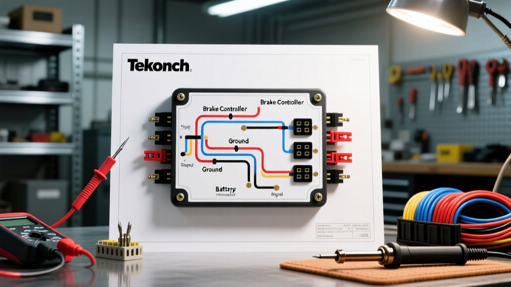
When servicing or modifying commercial landscaping equipment, interpreting a wiring diagram for Toro Z Master models requires more than just tracing 12V DC paths. It demands a rigorous understanding of safety interlocks, environmental sealing, and industry compliance standards. Commercial zero-turn mowers like the Toro Z Master 8000 Series (e.g., model 78315) and the 6000 Series operate in brutal, high-vibration, and moisture-heavy environments. A wiring failure here does not merely result in a dead battery; it can lead to catastrophic operator injury or fatal PTO (Power Take-Off) entanglement.
According to the U.S. Consumer Product Safety Commission (CPSC), riding mower incidents frequently involve unintended blade engagement or failure of the operator-presence system. Therefore, every electrical modification, repair, or diagnostic procedure must strictly adhere to the original equipment manufacturer (OEM) schematics and the ANSI/OPEI B71.4 safety standards for commercial mowers.
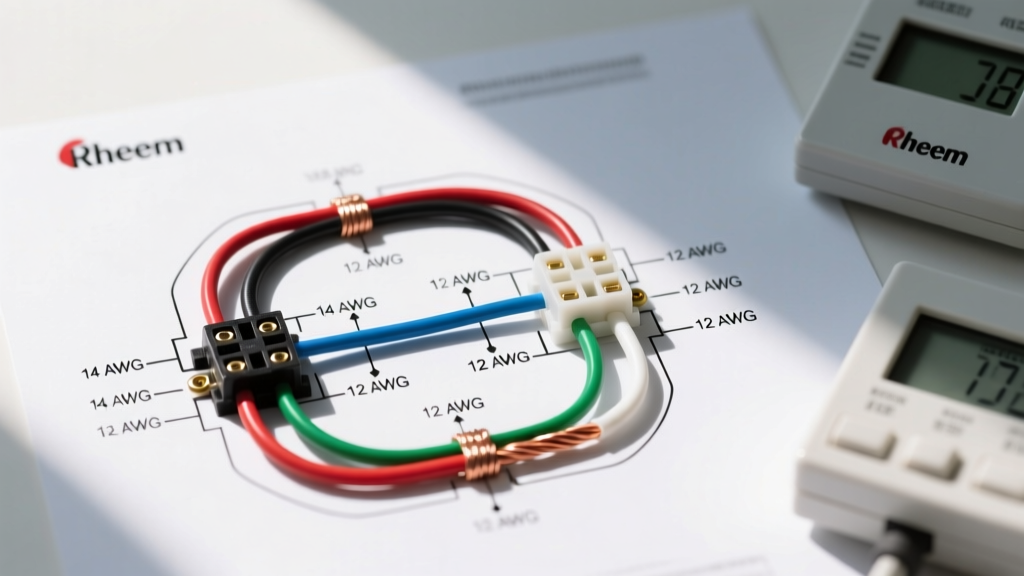
Wire Gauge, Ampacity, and Routing Specifications
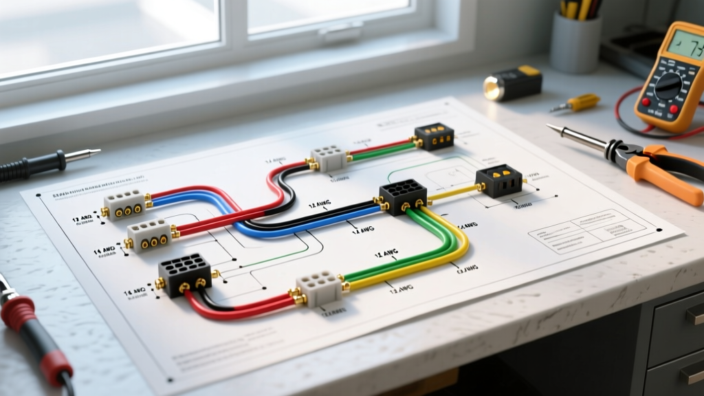
Before diving into the logic circuits, it is critical to verify that the physical wiring harness meets the amperage and thermal requirements of the mower. The Toro Official Manuals Database specifies high-temperature, cross-linked insulation for all engine-bay routing. Using standard PVC wire in a Z Master engine compartment will result in insulation melting against the exhaust manifold, leading to short circuits and potential fires.
| Circuit Function | Recommended AWG | Max Ampacity | Insulation Type | Routing Zone |
|---|---|---|---|---|
| Starter Motor & Battery Ground | 4 AWG | 200A+ | XLPE (Cross-linked) | Direct battery to solenoid |
| PTO Clutch Engagement | 10 AWG | 30A | SXL (High-Temp Auto) | Under chassis to deck |
| SIS Logic / SAM Module | 14 AWG | 15A | SXL / GXL | Protected dash harness |
| LED Dash / Hour Meter | 18 AWG | 5A | GXL | Interior control panel |
| Glow Plug Relay (Diesel) | 8 AWG | 60A | XLPE | Engine block direct |
Note: In 2026, the cost of OEM-spec SXL wire has stabilized, but technicians must ensure they are purchasing pure copper, not Copper-Clad Aluminum (CCA), which suffers from severe voltage drop under the heavy vibrational loads of a Z Master chassis.
The Safety Interlock System (SIS) and ANSI Compliance
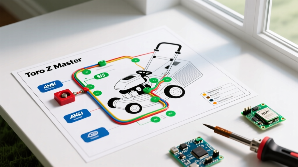
The core of any Toro Z Master wiring diagram is the Safety Interlock System (SIS). The Outdoor Power Equipment Institute (OPEI) enforces the ANSI B71.4 standard, which mandates that the mower blades must cease rotation within 5 seconds of the operator dismounting the seat, and the engine must shut down if the operator leaves the seat while the PTO is engaged or the parking brake is disengaged.
Discrete Relay Logic vs. Smart Interlock Modules (SAM)
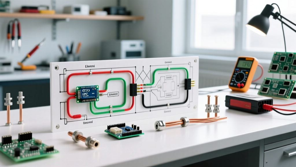
Older Z Master models utilized discrete relay logic, where the seat switch, PTO switch, and lap-bar (or brake) switches were wired in a complex series-parallel matrix to control the ignition coil ground. Modern Z Master 6000 and 8000 series mowers utilize a Smart Interlock Module (SAM). The SAM is a solid-state microcontroller that monitors the state of all safety switches. If the logic sequence is violated (e.g., PTO engaged + Seat empty + Brake released), the SAM cuts the ground path to the ignition kill relay or the fuel shutoff solenoid.
CRITICAL SAFETY WARNING: Bypassing the seat switch or SAM module by jumpering wires is a severe violation of OSHA workplace safety regulations and ANSI codes. Technicians caught bypassing interlocks on commercial fleet machines assume full liability for subsequent operator injuries. Always diagnose and replace faulty switches; never bypass them.
Step-by-Step SIS Troubleshooting Protocol
When a Z Master fails to crank or the PTO disengages unexpectedly, technicians must use a digital multimeter (DMM) to trace the logic faults. Follow this precise diagnostic sequence:
- Verify Base Voltage: Measure battery voltage at the SAM module power pin. It must read a minimum of 12.4V resting. A voltage below 11.8V will cause the SAM logic to reset erratically, mimicking a bad interlock switch.
- Test the Seat Switch Matrix: Toro uses dual-circuit seat switches (SPST-NO and SPST-NC) to prevent simple jumper-wire bypasses. Disconnect the switch and test for continuity. Circuit A should close when seated; Circuit B should open when seated. If both circuits show the same state, the switch diaphragm has failed.
- Check the PTO Switch Inrush: The PTO clutch (typically an Ogura or Warner Electric unit) draws 2.5A to 3.5A continuously, but inrush current can spike to 15A. Use a DMM with a min/max hold feature to check for voltage drops across the PTO relay contacts. A drop greater than 0.5V indicates pitted relay contacts requiring immediate replacement.
- Inspect the Brake/Lap Bar Microswitches: These switches are exposed to the most debris. Spray electrical contact cleaner into the microswitch actuator and cycle it 50 times. Check for intermittent continuity while wiggling the harness.
Gasoline vs. Diesel Z Master Wiring Differences
A common mistake in commercial fleet maintenance is applying a gasoline wiring diagram to a diesel Z Master. The 7500-D and 9000-D diesel models have fundamentally different engine-kill and starting architectures.
| Electrical Feature | Gasoline (6000/8000 Series) | Diesel (7500-D / 9000-D) |
|---|---|---|
| Engine Kill Mechanism | Ignition Coil Ground (12V) | Fuel Shutoff Solenoid (12V Pull/Push) |
| Glow Plug Circuit | Not Applicable | High-amp relay with 8-second timer module |
| SIS Logic Target | Ground-trigger Ignition Relay | SAM with isolated Fuel Solenoid Relay |
| Starter Draw Profile | 150A - 200A peak | 250A - 350A peak (High Compression) |
On diesel models, the SIS module must trigger the fuel shutoff solenoid to retract the fuel rack. If the wiring to this solenoid chafes against the hydrostatic pump housing—a common failure point on the 7500-D—the engine will continue to run even if the operator is thrown from the machine, creating a massive safety hazard.
Environmental Sealing and Connector Codes
Commercial mowers are pressure-washed weekly. Standard spade connectors will corrode within a single season, leading to high-resistance faults that the SAM module will interpret as an open safety switch, resulting in a no-start condition.
- Deutsch DT Series Connectors: Used for high-current connections like the PTO clutch and starter solenoid. These offer IP69K water ingress protection when properly sealed with the green wedge lock and silicone plugs.
- AMP Superseal 1.5: Utilized for the SAM module and sensor inputs. Ensure the secondary locking tab is fully engaged to prevent vibration-induced pin back-out.
- Heat Shrink & Dielectric Grease: Any inline splice made during a harness repair must use dual-wall, adhesive-lined heat shrink (minimum 3:1 shrink ratio). Apply Nyogel dielectric grease to all mating connector faces to prevent galvanic corrosion between copper and brass terminals.
Frequently Asked Questions (FAQ)
Can I use an automotive relay to replace the OEM Toro PTO relay?
While a standard 30A automotive ISO relay will physically fit and function temporarily, it lacks the sealed epoxy potting and vibration resistance of the OEM Toro relay. In commercial environments, standard automotive relays typically fail within 6 months due to moisture ingress and micro-vibrations. Always use the OEM sealed relay (typically $25-$40) to maintain IP67 compliance.
Why does my Z Master 8000 shut off when I release the lap bars, even with the brake on?
This is usually caused by a misadjusted brake microswitch or a faulty SAM module. The logic requires the brake switch to close (completing the ground path to the SAM) before the lap bar switches can open. If the brake switch is out of adjustment by even 2 millimeters, the SAM will not register the parking brake as engaged, and will kill the engine when the lap bars move to the neutral position.
How often should the wiring harness be inspected for code compliance?
Fleet managers should mandate a full harness and interlock inspection every 250 operating hours or at the start of the spring mowing season. This includes checking for chafing near the steering dampeners, verifying torque on the battery and starter solenoid lugs (typically 80-100 in-lbs), and testing the PTO blade-stop time to ensure it meets the ANSI 5-second maximum requirement.