
Decoding the Schematic: Your Blueprint for HVAC Diagnostics
When a central air conditioning system fails mid-summer, the difference between a costly service call and a rapid DIY fix often comes down to a single piece of paper taped to the inside of the condenser cabinet door. A central air conditioner electrical wiring diagram is not merely a map of where wires connect; it is a logical flowchart that dictates the exact sequence of operations required to initiate cooling. For technicians and advanced DIYers in 2026, mastering this diagram is the ultimate troubleshooting shortcut.
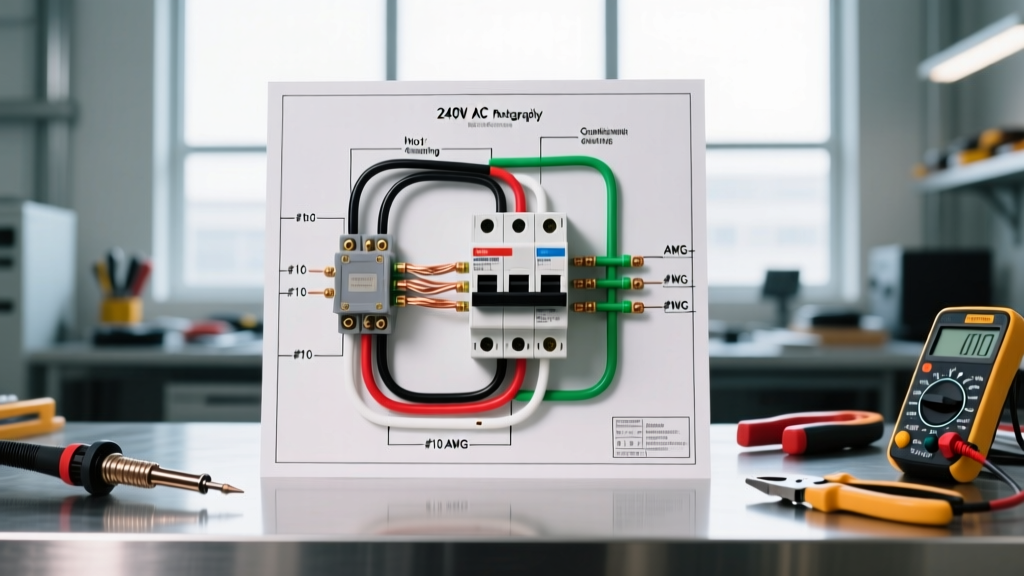
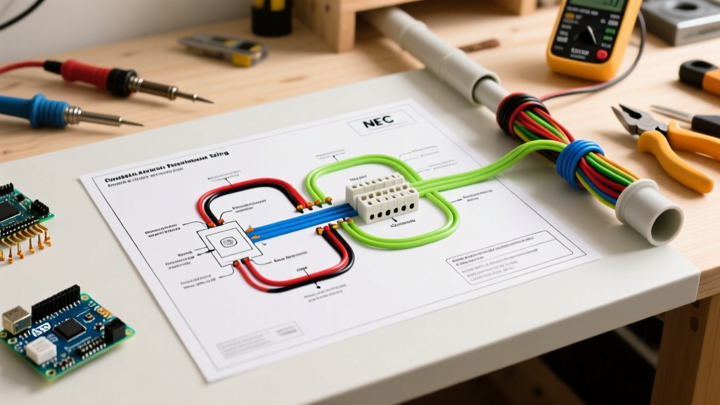
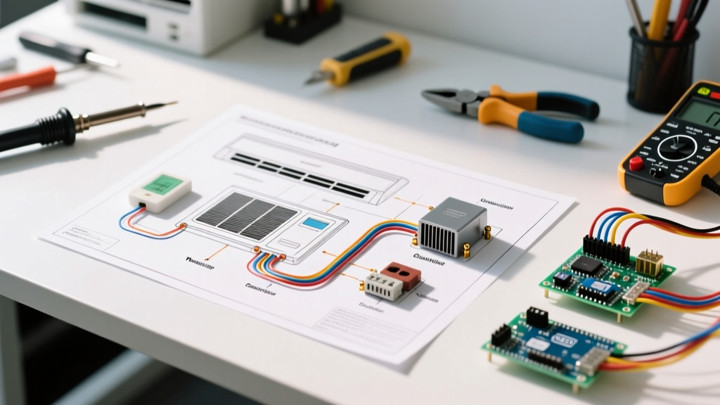
Most homeowners make the critical mistake of confusing the pictorial diagram with the ladder logic schematic. The pictorial drawing shows the physical layout of the components (where the contactor sits relative to the compressor), which is useful for reassembling parts but nearly useless for electrical diagnostics. The ladder diagram, however, abstracts the physical layout into pure electrical logic, displaying the 24-volt control circuits on one side and the 240-volt line circuits on the other. To troubleshoot effectively, you must exclusively use the ladder logic schematic.
Essential Diagnostic Arsenal for Diagram Tracing
Before you begin tracing circuits on your central air conditioner electrical wiring diagram, you need the right tools to measure the specific nodes identified on the schematic. Guessing leads to blown fuses and damaged control boards.
- True-RMS HVAC Multimeter: A standard multimeter will not accurately read the non-sinusoidal waveforms produced by modern variable-frequency drives (VFDs) in newer ECM fan motors. Invest in a True-RMS meter like the Fluke 116 HVAC Multimeter (approx. $220) or the Fieldpiece SC440 (approx. $360).
- Non-Contact Voltage Tester (NCVT): The Klein Tools NCVT-3 ($35) is essential for verifying the absence of voltage before touching any terminals, complying with basic safety protocols.
- Alligator Clip Test Leads: Essential for 'back-probing' contactor coils and pressure switches while keeping your hands safely away from live 240V terminals.
Phase 1: Tracing the 24-Volt Control Circuit
The control circuit is the brain of the AC unit. It operates at 24VAC, stepped down from the line voltage by a control transformer (typically rated at 40VA). When the thermostat calls for cooling, it closes the circuit between the R (24V Hot) and Y (Compressor Contactor) terminals.
The 'Divide and Conquer' Method for Blown Control Fuses
If your central air conditioner electrical wiring diagram shows a 3A or 5A fuse on the secondary side of the transformer and that fuse is blown, you have a dead short to ground. Do not simply replace the fuse; it will blow again instantly. Instead, use the diagram to isolate the short:
- Disconnect all field wiring: Remove the thermostat wires (R, Y, G, C) from the outdoor unit's terminal block.
- Test the transformer: With the field wires disconnected, measure across the transformer secondary. If you read 24VAC, the transformer and internal board are fine. The short is in the field wiring.
- Isolate the culprit: Reconnect the wires one by one. When you reconnect the Y (yellow) wire and the fuse blows (or the board LED flashes a short-circuit code), you know the short is in the yellow wire running between the air handler and the condenser, likely caused by a weed whacker or rodent damage.
Phase 2: Tracing the 240-Volt Line Circuit
The line circuit delivers the raw power required to run the compressor and the condenser fan motor. According to NFPA 70 (National Electrical Code) Article 440, this circuit requires a dedicated double-pole breaker sized to the Minimum Circuit Ampacity (MCA) listed on the unit's data plate.
When tracing the 240V circuit on your diagram, follow the path from the main disconnect (L1 and L2) through the high-pressure switch (if line-voltage rated, though most modern units use 24V logic for safety switches), into the contactor's electromagnetic coil, and finally through the contactor's heavy-duty contacts to the compressor and fan motor.
Pro-Tip: If the contactor coil is energized (you measure 24VAC across the A1 and A2 coil terminals) but the compressor and fan do not run, the contacts are likely pitted or carbon-fouled. Measure voltage across the contactor's line-side and load-side terminals. If you have 240V on the line side but 0V on the load side while the contactor is physically pulled in, the contactor has failed internally and must be replaced (typically a $15 to $45 part).
Diagnostic Matrix: Mapping Symptoms to Wiring Nodes
Use this matrix in conjunction with your specific unit's central air conditioner electrical wiring diagram to pinpoint failures rapidly.
| System Symptom | Diagram Node to Trace | Expected Multimeter Reading | Likely Failure Mode & Fix |
|---|---|---|---|
| Thermostat clicks, but nothing outside turns on. | Contactor Coil (A1 to A2) | 24VAC | Open coil or broken 24V wire. Replace contactor ($25) or splice wire. |
| Condenser fan runs, but compressor hums and trips breaker. | Compressor Run Capacitor (C to HERM) | Microfarads within 6% of rating | Weak/failed dual run capacitor. Replace with exact MFD rating ($20-$60). |
| Unit runs for 5 minutes, then shuts off completely. | High-Pressure Switch (HPS) in Y circuit | Continuity (0 Ohms) when closed | HPS tripped due to dirty condenser coils or restricted metering device. Clean coils. |
| Compressor short-cycles rapidly (on/off every 30 secs). | Low-Pressure Switch (LPS) & Time Delay Relay | 24VAC passing through LPS | Low refrigerant charge causing LPS to flutter, or failed anti-short-cycle timer. |
Real-World Case Study: The Ghost Voltage on a Goodman GSX16
Consider a scenario involving a popular 3-ton unit, the Goodman GSX160361. The homeowner reports the outdoor unit is completely dead, despite the indoor blower running. The indoor control board shows no error codes.
The Trace: Using the central air conditioner electrical wiring diagram, we locate the terminal strip where the 24V field wires land. We measure between C (Common) and Y (Compressor) at the outdoor terminal block. The meter reads 0VAC. However, measuring between R and C yields a stable 24VAC. This confirms the transformer is healthy, but the 'call for cooling' signal is not reaching the outdoor unit.
The Discovery: We move to the indoor air handler control board. Measuring between the Y terminal on the board and the C terminal on the board, we read 24VAC. The board is sending the signal. The fault lies in the 18-gauge solid copper thermostat wire running between the air handler and the condenser. A physical inspection reveals the wire was severed near the foundation wall by recent landscaping work. Splicing the 18-gauge wire with waterproof silicone-filled wire nuts restores the 24V logic path, and the contactor immediately pulls in.
Safety Protocols and Code Compliance
Troubleshooting live 240V circuits carries a severe risk of arc flash and electrocution. The OSHA Lockout/Tagout (LOTO) standard 1910.147 mandates that before removing any access panels or touching any internal wiring, the main disconnect switch must be pulled, locked, and tagged. Furthermore, you must use your NCVT and multimeter to verify a zero-energy state on both L1 and L2 at the contactor line-side terminals.
For units utilizing newer R-454B or R-32 mildly flammable refrigerants (standard in many 2025 and 2026 models), the wiring diagrams will include specific spark-proof relay enclosures and ground-fault monitoring circuits. Never bypass these safety interlocks to force a compressor to run, as doing so violates ENERGY STAR and EPA Section 608 safety regulations and creates a severe explosion hazard in the presence of a refrigerant leak.
Final Diagnostic Advice
Always photograph the central air conditioner electrical wiring diagram before disconnecting any wires. Modern HVAC systems utilize complex multi-stage wiring, and relying on memory when re-terminating a 7-conductor thermostat cable or a 4-wire dual capacitor is a recipe for catastrophic component failure. Let the schematic guide your multimeter, trust the readings over your assumptions, and you will systematically eliminate every electrical fault in the system.