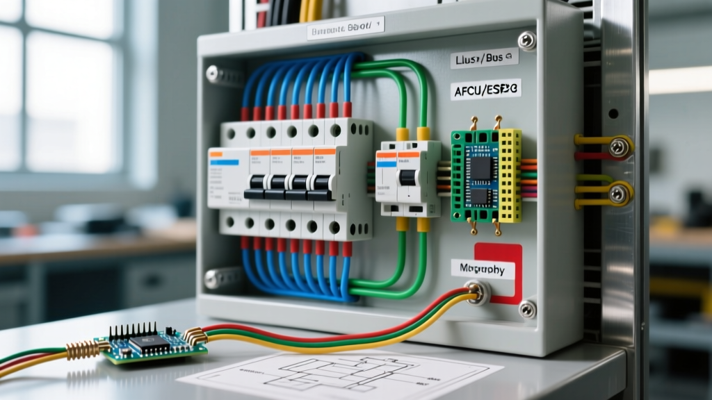

The Critical Role of Schematic Symbols in Panel Design
When upgrading a residential or commercial electrical panel, misinterpreting a single line on a blueprint can lead to catastrophic failures, code violations, or severe arc flash hazards. Understanding electrical wiring schematic symbols is not just an academic exercise; it is the foundational skill required to navigate panel schedules, design subpanel feeds, and ensure compliance with the latest National Electrical Code (NEC) standards. As we move through 2026, the adoption of smart panels and advanced fault-protection breakers has introduced new schematic notations that every electrician and serious DIYer must master.
In this guide, we decode the specific electrical wiring schematic symbols used in panel and breaker layouts, translating abstract lines into actionable wiring strategies for Square D, Eaton, and Siemens load centers.
Essential Panel & Breaker Schematic Symbols
Before tackling complex multi-wire branch circuits (MWBCs) or transformer feeds, you must fluently read the core symbols found on any panel schematic. The table below maps standard schematic symbols to their physical panel components and real-world applications.
| Schematic Symbol | Component Name | Panel Application & 2026 Context |
|---|---|---|
| ┃━┫ (Vertical line with crossbar) | Single-Pole Circuit Breaker | Standard 120V, 15A/20A branch circuits. Represented as a single switch on the hot bus bar. |
| ┃━┫ ┃━┫ (Linked crossbars) | Two-Pole Circuit Breaker | 240V appliances (HVAC, dryers). The mechanical tie-bar is often denoted by a dashed line linking the poles. |
| ⏚ (Three descending horizontal lines) | Earth Ground / Grounding Bus | The Equipment Grounding Conductor (EGC) termination point. Crucial for fault current clearing. |
| ⊥ (Inverted T or horizontal line with vertical tick) | Neutral Bus Bar | Termination for grounded conductors. Must be isolated from the ground bus in subpanels per NEC Article 250. |
| ≋ (Sine wave inside a box) | AFCI Breaker (Arc Fault) | Required in 2026 for most dwelling unit living spaces (NEC 210.12). Denotes microprocessor-based arc detection. |
| ∿ (Sine wave with 'GF' or test button icon) | GFCI Breaker (Ground Fault) | Used for wet locations. Monitors current imbalance between hot and neutral (trips at 4-6mA). |
| ⊗ (Circle with an X) | Main Service Disconnect | The primary shut-off for the panel. In 2026, often integrated with smart metering modules. |
Advanced Breaker Symbols: AFCI, GFCI, and Dual-Function
Modern panel schematics frequently utilize specialized symbols to denote advanced protection breakers. Misreading these can result in purchasing the wrong hardware, leading to failed inspections and wasted budget.
Dual-Function (DF) Breaker Notations
A Dual-Function breaker combines both AFCI and GFCI protection in a single chassis. On a schematic, this is typically represented by a breaker symbol containing both the arc wave (≋) and the ground fault wave (∿), often enclosed in a single bounding box with the letters "DF" or "CAFCI/GFCI".
- Real-World Product Match: Square D QO120DF (120V, 20A Dual Function). Retailing around $68 in 2026, these are mandatory for kitchen and laundry circuits where both arc and ground fault protection are required by the NEC.
- Wiring Specifics: The schematic will show a pigtail wire (usually a white coiled line) connecting to the neutral bus, alongside the load neutral and hot wires. Failing to connect the pigtail to the neutral bus will cause the breaker to trip immediately upon energization.
Tandem and Quad Breaker Schematics
When panel space is limited, schematics will show tandem (duplex) breakers. These are denoted by a single breaker slot on the bus bar diagram that splits into two distinct circuit lines.
Expert Warning: Never install a tandem breaker (e.g., Eaton BR2020T) in a panel that does not explicitly accept them. Schematics for older panels will show a "Notched" or "Rejected" bus bar symbol (a bus stab with a small cross through it), indicating that the physical bus stab lacks the rejection clip required to prevent tandem insertion. Forcing a tandem breaker onto a standard stab can cause bus bar arcing and panel fires.
Grounding vs. Bonding: Symbols That Prevent Fire Hazards
The most common fatal error in subpanel wiring is bonding the neutral to the ground. Schematic symbols make the distinction clear, provided you know what to look for.
The Main Panel vs. Subpanel Schematic Difference
In a Main Service Panel schematic, you will see a Bonding Jumper symbol (a heavy dashed line or a specific green screw icon) connecting the Neutral Bus (⊥) to the Ground Bus (⏚). This is the only location in the electrical system where the grounded (neutral) and grounding conductors are allowed to touch, establishing the zero-reference potential.
In a Subpanel Schematic, this bonding symbol is explicitly absent. Instead, you will see a 4-wire feed symbol: two hot lines (L1, L2), one isolated neutral (N), and one equipment ground (EGC).
- Wire Gauge Specifics: For a standard 100A subpanel feed, the schematic will specify 4 AWG copper or 2 AWG aluminum for the hots and neutral, with an 8 AWG copper EGC.
- 2026 Code Update: Recent NEC adoptions strictly enforce the removal of the bonding strap in subpanels. If your schematic shows a bonded subpanel, it is an outdated drawing and must be revised before pulling wire.
Reading a Commercial Panel Schedule Diagram
Commercial panel schedules are dense matrices of electrical wiring schematic symbols. To decode them efficiently, follow this systematic flow:
- Identify the System Type: Look at the top header. A symbol showing "3Φ, 4W, 208Y/120V" indicates a 3-phase Wye system. This tells you that single-pole breakers yield 120V, while two-pole breakers yield 208V (not 240V).
- Trace the Bus Bar Phasing: Commercial panels use an A-B-C phase rotation. The schematic will color-code or label the bus stabs (e.g., Black-Red-Blue). Ensure 208V loads are balanced across different phase pairs (AB, BC, CA) to prevent neutral overload.
- Check the AIC Rating: Look for the Available Interrupting Current symbol (often a lightning bolt inside a circle with a value like "22kAIC"). If your utility transformer delivers 30kAIC of fault current, standard 10kAIC breakers will violently fail during a short circuit. You must specify high-AIC breakers (e.g., Eaton BAB series at 22kAIC, costing roughly $45/pole compared to $12 for standard BR models).
- Verify Continuous Load Derating: If a circuit powers a continuous load (running 3+ hours), the schematic will often feature an asterisk (*) or a specific multiplier symbol (x1.25). A 20A breaker on the schematic actually requires a 16A maximum continuous load.
Real-World Troubleshooting: Tracing a Ghost Voltage
Schematic symbols are invaluable when troubleshooting existing panels. Consider a scenario where a 120V receptacle reads 40V on a digital multimeter—a classic "ghost voltage" caused by a broken neutral.
By consulting the panel's Multi-Wire Branch Circuit (MWBC) schematic, you can identify if the receptacle shares a neutral with another circuit. The schematic will show two single-pole breakers tied together with a handle-tie symbol (a bracket linking two adjacent breaker switches) sharing a single neutral line returning to the bus.
If the handle tie is missing in the physical panel, or if the two breakers were accidentally placed on the same phase (e.g., both on Phase A instead of Phase A and Phase B), the shared neutral will carry the sum of the currents rather than the difference. This causes the neutral wire to overheat, melt the insulation, and eventually break, resulting in the ghost voltage you are measuring at the outlet. The schematic immediately reveals the design intent, allowing you to verify phase placement and handle-tie compliance without guessing.
Authoritative References and Standards
To ensure your panel designs and schematic interpretations meet the highest safety standards, always cross-reference your work with current industry codes. For the most accurate and up-to-date electrical wiring schematic symbols and panel wiring rules, consult the National Fire Protection Association (NFPA) NEC Guidelines. Additionally, for workplace safety requirements regarding panel clearances and arc flash labeling based on schematic fault calculations, review the OSHA Electrical Safety Standards. Mastery of these symbols bridges the gap between theoretical design and a safe, code-compliant physical installation.