
Decoding the STX38 Electrical Architecture
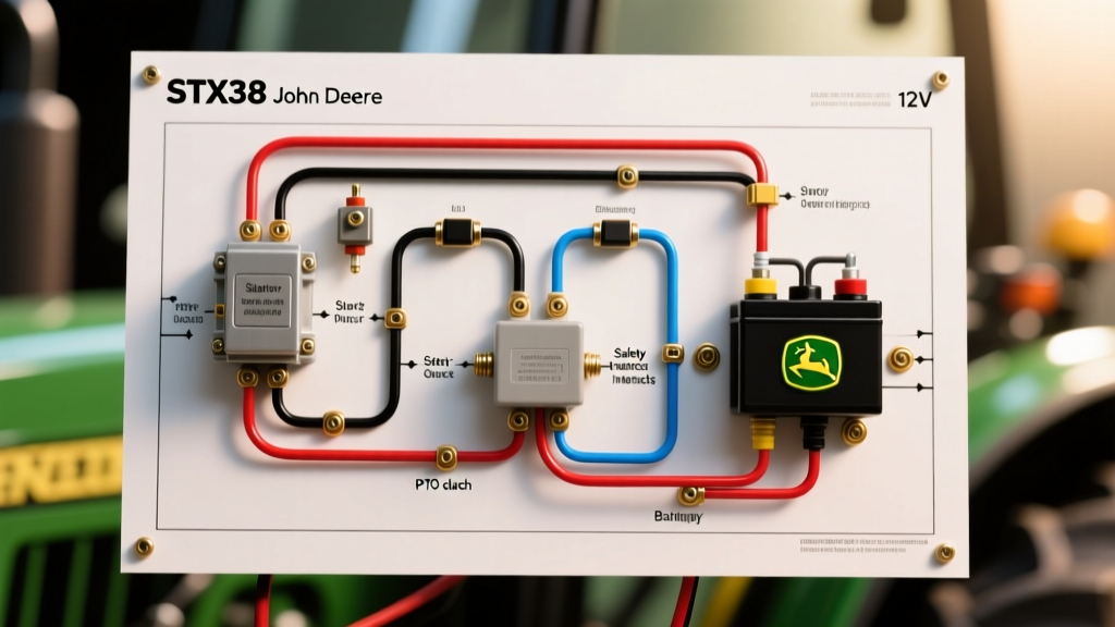
The John Deere STX38, primarily produced between 1988 and 1997, remains one of the most reliable compact lawn tractors ever built. Powered predominantly by the 13 HP Kawasaki FC420V engine, its 12-volt electrical system is robust but prone to harness degradation, corroded spade connectors, and failing safety interlocks after decades of use. Understanding the wiring diagram for STX38 John Deere models requires breaking the system down into three distinct operational zones: the cranking circuit, the charging/stator circuit, and the accessory/safety interlock network.
Unlike modern tractors that rely on solid-state CAN bus networks or complex ECU modules, the STX38 utilizes a hardwired analog relay system. This makes it an ideal candidate for DIY rewiring and bench-level troubleshooting using a standard digital multimeter (DMM). Below, we detail the exact terminal mappings, resistance values, and voltage drop thresholds required to restore an STX38 to factory electrical specifications.
Core Components and Wire Gauge Specifications
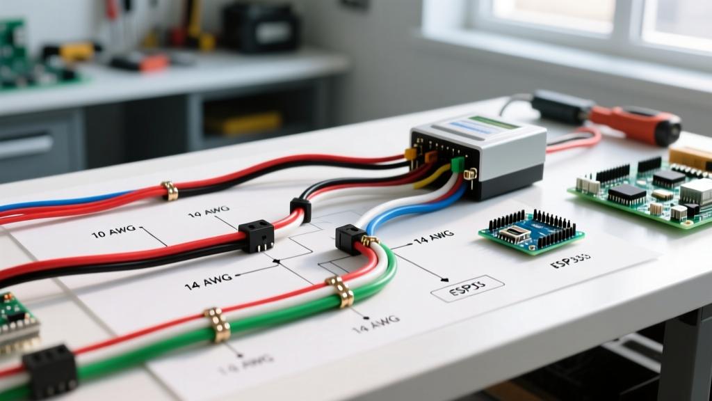
When replacing brittle OEM wiring, adhering to proper AWG (American Wire Gauge) standards is critical to prevent voltage drop and thermal runaway. According to general wiring standards verified by UL wire and cable testing guidelines, using undersized wire for inductive loads like starter solenoids and PTO clutches will result in premature component failure.
| Circuit Zone | Recommended AWG | Insulation Type | Typical Wire Color (OEM) |
|---|---|---|---|
| Battery to Solenoid | 10 AWG | XLPE or PVC (UL 1015) | Red |
| Solenoid to Starter Motor | 10 AWG | XLPE or PVC (UL 1015) | Red |
| Electric PTO Clutch Feed | 12 AWG | Cross-linked Polyethylene | White / Red Tracer |
| Ignition & Interlock Logic | 16 to 18 AWG | PVC | Black, Green, Yellow |
Ignition Switch Terminal Mapping (5-Pin Magneto)
The STX38 utilizes a 5-pin ignition switch (commonly replaced by OEM part AM107134 or generic equivalents). Because the Kawasaki FC420V uses a magneto ignition system rather than a 12V battery-fed coil, the switch does not supply power to the ignition coil. Instead, it grounds the magneto primary winding to kill the engine.
| Terminal | Designation | Function in 'RUN' Position | Function in 'OFF' Position |
|---|---|---|---|
| B | Battery | Receives 12V+ from 40A Maxi-Fuse | Receives 12V+ (Constant) |
| S | Starter | Open (No continuity) | Open |
| I | Ignition/Accessory | Outputs 12V+ to PTO relay & dash | Open (0V) |
| L | Lights | Outputs 12V+ to headlight circuit | Open (0V) |
| M | Magneto Kill | Open (Engine runs) | Shorts to Ground (Engine dies) |
The Safety Interlock Cascade
Compliance with modern safety standards, as outlined by the Outdoor Power Equipment Institute (OPEI), mandates that riding mowers prevent cranking if the PTO is engaged and must kill the engine if the operator leaves the seat without the parking brake set. The STX38 achieves this via a cascade of normally-open (NO) and normally-closed (NC) microswitches.
Testing the Seat and Brake Switches
Faulty interlocks are responsible for over 60% of 'no-crank' complaints on the STX38. The starter solenoid trigger wire (typically yellow or red with a tracer) must pass through the brake switch and the PTO switch before reaching the solenoid's 'S' post.
- Brake Switch: Normally Open (NO). Closes only when the brake pedal is fully depressed. Set your DMM to continuity mode. Press the pedal; the meter should beep. If it clicks intermittently, the physical actuator rod is bent or the switch plunger is fouled with grass debris.
- Seat Switch: Normally Closed (NC) in the kill circuit, but integrated into the starting circuit as an open bypass. If the operator is not in the seat, the seat switch completes a ground path to the ignition module, killing the spark. Never permanently bypass the seat switch; instead, clean the plunger mechanism and verify the 15-20 lb activation weight threshold.
Electric PTO Clutch Wiring and Diagnostics
Later 'Black Deck' STX38 models feature an electric PTO clutch (often a Warner Electric or Xtreme brand). This is an inductive load that draws significant current upon engagement and requires precise wiring to prevent voltage drop.
PTO Clutch Diagnostic Matrix
| Test Parameter | Expected Value | Failure Mode & Correction |
|---|---|---|
| Coil Resistance (Ohms) | 2.5 Ω to 4.0 Ω | Below 2.0 Ω: Internal short. Above 5.0 Ω: Open coil. Replace clutch assembly. |
| Voltage at Clutch Plug (Running) | 13.2V to 13.8V DC | Below 12.0V: Voltage drop in harness or failing stator. Check PTO relay contacts. |
| Air Gap (Feeler Gauge) | 0.012' to 0.015' | Exceeds 0.020': Clutch slips under load, generates excess heat, and melts wiring pigtails. |
Kawasaki FC420V Stator and Regulator Testing
The STX38 charging system relies on an alternator stator located beneath the engine flywheel, paired with a finned aluminum voltage regulator/rectifier. A common misdiagnosis is replacing the battery when the stator is actually failing to output sufficient AC voltage.
- Locate the Stator Plug: Unplug the 2-pin (or 3-pin with center ground) connector emerging from the engine block, usually located near the oil dipstick.
- AC Voltage Test: Set your multimeter to AC Volts (V~). Start the engine and run it at full throttle (3600 RPM). You should read between 28V AC and 35V AC across the two stator pins. If you read less than 20V AC, the stator windings are burnt or the flywheel magnets have weakened.
- DC Output Test: Reconnect the stator to the regulator. Set your multimeter to DC Volts (V⎓). Measure across the battery terminals at full throttle. The reading must be 13.8V to 14.2V DC. If it reads exactly battery voltage (12.6V) and drops as the engine runs, the regulator/rectifier has failed internally.
Performing a Voltage Drop Test on the Cranking Circuit
If your STX38 starter clicks but the engine turns over slowly, do not immediately replace the starter motor. Perform a voltage drop test to find hidden resistance in the 30-year-old wiring harness.
Procedure: Set your DMM to DC Volts. Place the red probe on the battery's positive post and the black probe on the starter motor's main lug. Have an assistant crank the engine. A reading above 0.5V indicates high resistance in the positive cable, the 40A maxi-fuse holder, or the solenoid internal contacts. Repeat on the ground side (black probe on battery negative post, red probe on starter casing) to verify engine block grounding.
Harness Restoration and OEM Sourcing
When the main harness insulation begins to flake off, exposing bare copper to moisture and fertilizer chemicals, a full replacement is safer than piecemeal splicing. You can source complete OEM replacement harnesses and updated wiring schematics directly through the official John Deere Parts and Service portal using your tractor's serial number (located on the frame beneath the seat pan).
For DIY repairs, always use marine-grade adhesive-lined heat shrink tubing and apply dielectric grease (such as Permatex 22058) to all exposed spade connectors, particularly the PTO clutch plug and the stator connector, which are highly susceptible to water intrusion during deck washing.