
The Evolution of Security Wiring in 2026
Designing a robust physical security infrastructure requires more than just connecting sensors to a control panel. A comprehensive wiring diagram for security system planning serves as the foundational blueprint for low-voltage integrity, signal supervision, and long-term scalability. In 2026, the landscape of intrusion detection has shifted heavily toward hybrid architectures, blending traditional hardwired analog zones with high-speed addressable data loops and Power over Ethernet (PoE) integrations. Whether you are retrofitting a commercial warehouse or planning a high-end residential deployment, understanding how to draft, read, and execute these diagrams is critical for passing inspections and ensuring life-safety compliance.
Deconstructing the Wiring Diagram for Security System Architectures
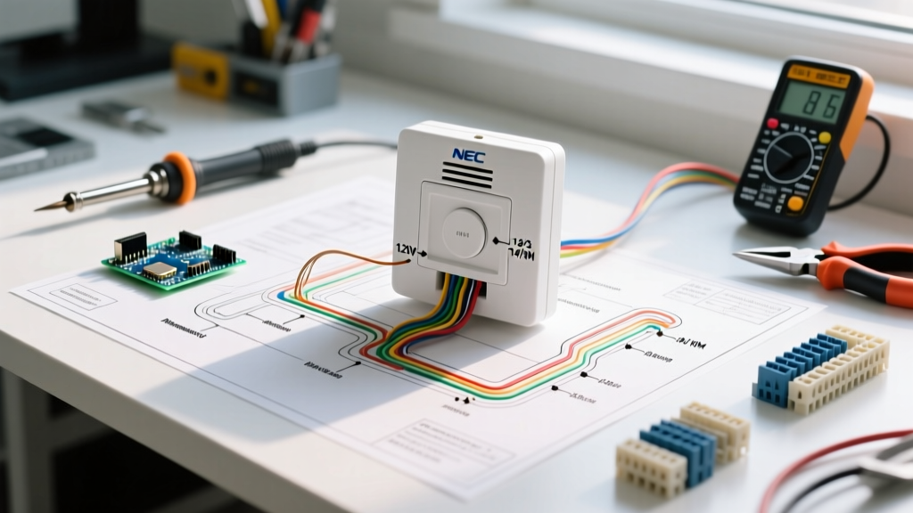
When you examine a professional wiring diagram for security system deployments, it is typically divided into three distinct subsystems: the input (initiating devices), the control (panel and communicators), and the output (notification appliances). Modern panels like the DSC PowerSeries Neo HS2032 or the Bosch B9512G utilize proprietary bus topologies that drastically alter how wires are routed compared to legacy home-run configurations.
Addressable Loops vs. Conventional Hardwired Zones
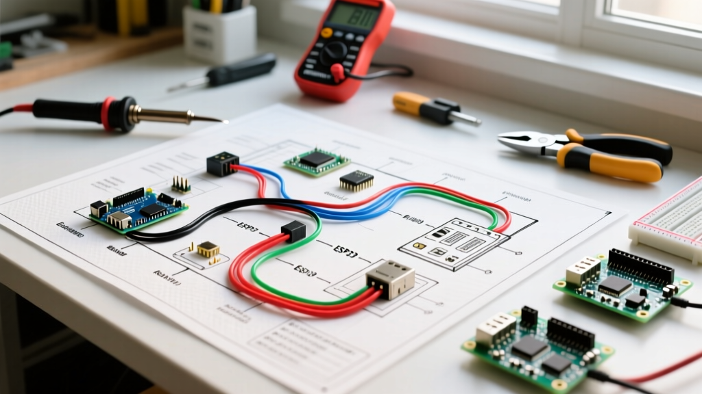
Conventional wiring requires a dedicated home-run cable from every single sensor back to the panel's zone terminals. While simple to troubleshoot, it consumes massive amounts of copper and conduit space. Addressable wiring, such as DSC's Corbus or Bosch's SDI2, utilizes a 4-wire daisy-chain or T-tapped topology. This allows dozens of sensors to share a single cable run, with microprocessors in each device reporting their specific status back to the panel. Your diagram must clearly distinguish between these two wiring styles, typically using solid lines for conventional zones and dashed lines for addressable data loops.
Wire Gauge and Cable Selection Matrix
Selecting the correct cable type is where most installation failures originate. Using undersized wire for notification appliances leads to voltage drop, resulting in sirens that fail to sound during an alarm event. Below is a standard specification matrix for 2026 commercial and residential deployments.
| Cable Type / Standard | Gauge & Conductors | Primary Application | Max Recommended Run | Est. Bulk Cost (2026) |
|---|---|---|---|---|
| Belden 9942 (or equiv) | 22 AWG, 4-Conductor | Keypads, Addressable Loops | 500 ft (152 m) | $145 / 1000 ft |
| Belden 8760 (or equiv) | 18 AWG, 2-Conductor | Sirens, Strobes, Power | 1,000 ft (304 m) | $185 / 1000 ft |
| Belden 9941 (or equiv) | 18 AWG, 4-Conductor | High-Current Access Control | 800 ft (243 m) | $210 / 1000 ft |
| Cat6a UTP (Plenum) | 23 AWG, 8-Conductor | IP Cameras, PoE, IP Intercoms | 328 ft (100 m) | $260 / 1000 ft |
Pro Tip: Always specify plenum-rated (CMP/FPLP) cables when routing through HVAC return air spaces. Failing to do so is a direct violation of NEC Article 725 and will result in an immediate failed inspection in commercial buildings.
Power Supply and Battery Backup Calculations
A wiring diagram is incomplete without a detailed load calculation sheet. According to NFPA 72 guidelines, life-safety and commercial security systems must maintain 24 hours of standby battery power, followed by 5 minutes of full alarm load. To calculate the required Sealed Lead Acid (SLA) battery size, use the following formula:
(Standby Current in Amps × 24) + (Alarm Current in Amps × 0.083) = Minimum Amp-Hours (Ah)
Real-World Example:
If your panel, 4 keypads, and 20 wireless transceivers draw a combined 650mA (0.65A) in standby, and your dual 110dB sirens and strobes draw 2.5A during an alarm:
(0.65 × 24) + (2.5 × 0.083) = 15.6 + 0.207 = 15.807 Ah
In this scenario, your diagram must specify a 17Ah or dual 8Ah SLA battery bank, alongside an auxiliary power supply (like the Altronix SMP3) if the panel's internal transformer cannot handle the charging current.
End-of-Line (EOL) Resistor Placement and Supervision
Every conventional zone on a security panel requires an End-of-Line (EOL) resistor to supervise the wiring against tampering, cuts, or shorts. The most common mistake made by novice installers is placing the EOL resistor at the control panel terminals. This completely defeats the supervisory purpose, as a cut wire between the panel and the sensor will not trigger a trouble condition.
Standard EOL Resistor Values by Manufacturer
- Honeywell / Ademco Vista Series: 2,000 Ohm (2kΩ) - Red/Black/Red
- DSC PowerSeries / Neo: 5,600 Ohm (5.6kΩ) - Green/Blue/Red
- Bosch Solution Series: 2,200 Ohm (2.2kΩ) - Red/Red/Red
- Interlogix / GE NetworX: 3,300 Ohm (3.3kΩ) - Orange/Orange/Red
Your wiring diagram must explicitly note the resistor value and mandate that it is installed inside the sensor housing or at the very last device on a daisy-chained loop, physically spliced in series with the sensor's normally closed (NC) contacts.
Physical Routing and EMI Mitigation
Low-voltage security wiring is highly susceptible to Electromagnetic Interference (EMI) and Radio Frequency Interference (RFI). When drafting your physical routing plan, you must adhere to strict separation distances from high-voltage AC mains. NEC Article 725 and general OSHA electrical safety standards dictate that Class 2 and Class 3 low-voltage cables must not be run in the same conduit, junction box, or cable tray as 120V/240V AC power lines unless separated by a continuous, firmly fixed barrier.
- Maintain a 12-inch minimum separation between alarm cables and parallel AC wiring to prevent 60Hz hum and false zone trips.
- Cross AC lines at 90-degree angles when intersection is unavoidable to minimize inductive coupling.
- Ground shields at one end only: If using shielded cable (like Belden 8760) for environments with high RF noise, connect the drain wire to the panel's earth ground terminal only. Leaving the shield floating at the sensor end prevents ground loops, which can cause erratic keypad behavior and communication failures.
Common Wiring Failure Modes and Troubleshooting
Even with a perfect wiring diagram for security system layouts, field execution can introduce faults. Here are the most common edge cases and how to diagnose them:
- Voltage Drop on Siren Circuits: If a 12V siren measures only 9.5V at the end of a 400-foot run of 22 AWG wire, it will sound weak or fail entirely. Fix: Upgrade to 18 AWG wire or install a local auxiliary power supply with a relay triggered by the panel's PGM (Programmable Output).
- Addressable Loop Polling Errors: If a Corbus or SDI2 loop constantly drops devices, check for 'star' or 'hub-and-spoke' wiring topologies. Addressable loops require strict daisy-chain or T-tap configurations with maximum stub lengths (usually under 10 feet). Long stubs cause signal reflections that corrupt data packets.
- Phantom Alarms on Foil Window Sensors: Window foil tape is highly sensitive to capacitance changes. If wires are routed too close to metal window frames without proper insulation, moisture and temperature shifts will cause false trips. Use dedicated 22 AWG twisted pair with a ground shield for these specific zones.
Frequently Asked Questions
Can I use Cat5e or Cat6 for traditional analog alarm zones?
Yes, but with caveats. Cat5e/Cat6 uses 24 AWG solid copper, which is thinner than standard 22 AWG alarm wire. This increases resistance and limits your maximum run length by roughly 20%. Furthermore, the twisted pairs in Ethernet cable are optimized for high-frequency data, not low-frequency analog signals. If you use Cat6 for analog zones, you must pair the wires correctly (e.g., using the solid blue and blue/white stripe for a single zone) to maintain the twist rate and reject EMI. Never use Copper-Clad Aluminum (CCA) Ethernet cable for security systems; it is brittle, prone to oxidation, and violates fire codes.
How do I wire a dual-technology (PIR + Microwave) motion sensor?
Dual-tech sensors require more current than standard PIRs (often 35mA to 60mA). Your wiring diagram must account for this increased load on the auxiliary power bus. Wire the PIR and Microwave alarm relays in series for a single normally-closed zone loop, and wire the tamper switch to a separate 24-hour supervisory zone. Always verify that your panel's AUX+ terminal can supply the cumulative current of all connected motion sensors; if not, route the red (power) wire to a dedicated Altronix power distribution board.