
The Critical Role of the Schematic Electrical Wiring Diagram in Installation Planning
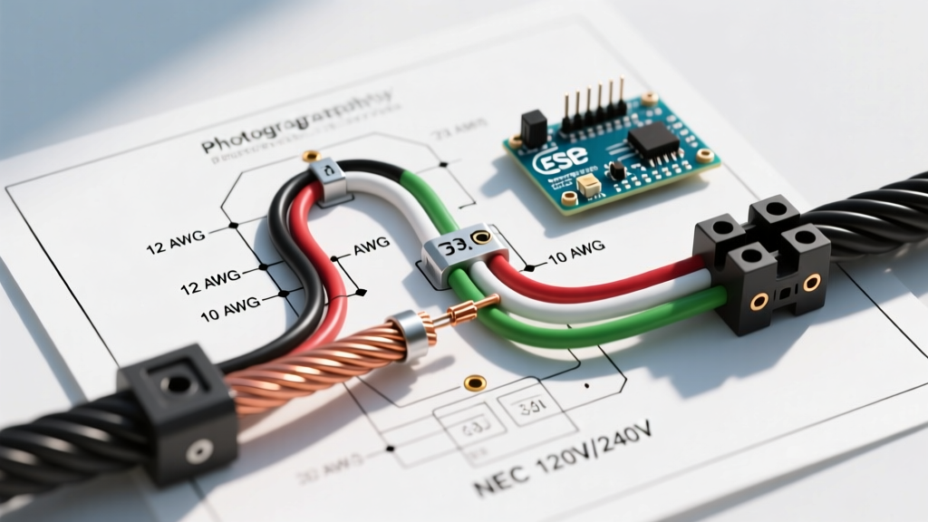
Before a single foot of copper is pulled through conduit, a successful electrical installation relies entirely on the accuracy of its planning phase. While physical wiring diagrams show you where wires route, the schematic electrical wiring diagram dictates how the circuit actually functions. It is the logical blueprint of your system. Misinterpreting a schematic during the planning stage doesn't just lead to inefficient routing; it results in catastrophic failures, tripped breakers, and severe code violations under the latest National Electrical Code (NEC) standards.
This installation planning guide bridges the gap between abstract logic and physical execution. We will break down how to decode schematics, trace loads, and translate logical nodes into physical junction box layouts for commercial and industrial projects in 2026.
Decoding the Schematic: Symbols vs. Physical Reality
A common pitfall for junior technicians is treating a schematic like a physical map. In a schematic electrical wiring diagram, proximity does not equal physical closeness. Two components drawn side-by-side might be located in entirely different control panels. To plan your installation accurately, you must map standard IEEE and IEC symbols to their physical hardware equivalents.
| Symbol Designation | Standard Reference | Physical Component Example | Installation Planning Action |
|---|---|---|---|
| Normally Open (NO) Contact | IEEE 315 / IEC 60617 | Eaton XTCE009B10 Contactor | Verify control coil voltage (e.g., 120VAC vs 24VDC) matches the PLC output card specs. |
| Thermal Overload Relay | NEMA ICS 2 | Allen-Bradley 193-EIO Thermal Unit | Ensure physical dial is set exactly to the motor's Full Load Amps (FLA) on the nameplate. |
| Variable Frequency Drive (VFD) | Manufacturer Specific | Yaskawa GA800 Series | Plan for dedicated grounding bus and shielded VFD cable (e.g., Belden 14AWG 4-conductor) to mitigate EMI. |
| Current Transformer (CT) | IEEE C57.13 | CR Magnetics CR4160-100 | Account for physical window size (e.g., 1.5") when selecting conduit and wire bundling. |
Phase 1: Pre-Installation Load Calculation and Circuit Tracing
You cannot size your wire or select your breakers without first tracing the logical loads on your schematic electrical wiring diagram. This phase prevents the costly mistake of pulling 12 AWG wire for a circuit that logically requires 10 AWG due to continuous load derating.
Step-by-Step Tracing Methodology
- Identify the Power Source Node: Locate the main disconnect or transformer secondary on the schematic (e.g., L1, L2, L3 for 480V 3-phase, or X1, X2 for 120V control).
- Trace Branch Paths: Follow the line from the source through the overcurrent protection device (fuse or breaker symbol). Note the breaker sizing indicated on the drawing (e.g., "20A/3P").
- Calculate Total Volt-Amps (VA):strong> Sum the VA of all downstream components on that specific branch. For a 120V control circuit powering four contactor coils rated at 150VA each, your total load is 600VA (5 Amps).
- Apply NEC Continuous Load Rules: If the circuit will be energized for 3 hours or more, multiply the calculated amperage by 1.25. In our example, 5A x 1.25 = 6.25A. This confirms a 14 AWG wire (rated 15A) and a 15A breaker are sufficient, but upgrading to 12 AWG is recommended for voltage drop mitigation over long runs.
Pro-Tip for 2026 Installations: Always cross-reference your schematic's calculated voltage drop against the physical routing distance. The Occupational Safety and Health Administration (OSHA) and NEC Article 210.19(A)(Informational Note) recommend keeping branch circuit voltage drop under 3%. Use a digital voltage drop calculator app during the planning phase to adjust wire gauges before purchasing materials.
Phase 2: Translating Logical Nodes to Physical Routing
Once the electrical logic is verified, the schematic electrical wiring diagram must be translated into a physical termination plan. Schematics use "node numbers" or "wire numbers" to indicate electrical continuity. Every wire with the same number on the schematic must be physically connected, regardless of how many terminal blocks it passes through.
Terminal Block Mapping Strategy
Modern industrial panels rely heavily on DIN-rail terminal blocks. When planning your panel layout, use the schematic to build a termination matrix. For instance, if the schematic shows wire "104B" connecting a PLC output to a relay coil, and then jumping to an indicator light, you must plan for a multi-level terminal block (like the Phoenix Contact PTIO 2.5 series) or a physical jumper bar to distribute that single node to three physical wires.
- Internal Panel Wiring: Use flexible, stranded wire (e.g., MTW or THHN in conduit) for door swings and internal routing. Plan for 18 AWG for control signals and 14-10 AWG for power.
- Field Wiring Boundaries: The schematic usually denotes a heavy dashed line representing the "panel boundary." Plan your physical terminal strips exactly at this boundary to separate internal factory wiring from external field wiring.
- Shield Grounding: If the schematic shows a shield drain wire connected to ground at the drive end only (to prevent ground loops), explicitly mark this on your physical routing plan to ensure the field crew does not ground both ends.
Essential Hardware and Software for 2026 Installations
Interpreting complex schematics and planning installations requires the right tools. Relying on printed 11x17 paper sheets is obsolete for large-scale commercial projects.
- Bluebeam Revu (approx. $349/year): Essential for marking up PDF schematics, performing digital takeoffs for wire lengths, and hyperlinking schematic pages to physical panel layouts.
- Fluke T6-1000 FieldLogger ($250 - $280): During the commissioning phase of your installation, this tool allows you to verify the schematic's logic against physical reality without stripping wire insulation, using FieldSense technology.
- AutoCAD Electrical 2026 (approx. $1,900/year): If you are modifying the schematic during the as-built phase, this software automatically updates wire numbers and terminal plans, preventing discrepancies between the drawing and the physical installation.
Edge Cases: When the Schematic Electrical Wiring Diagram Lies
In retrofit and expansion projects, the schematic you are handed may not reflect the current state of the facility. "As-built" drawings are notoriously inaccurate if previous contractors failed to redline their changes.
The "Ghost Voltage" Trap: Schematics rarely account for capacitive coupling in long, unshielded parallel cable runs. You might trace a schematic showing a discrete 24VDC input to a PLC, but measure 12VAC on the physical wire due to adjacent 480V VFD cables. During planning, if the schematic shows long parallel runs of low-voltage and high-voltage signals, you must proactively specify physical separation (minimum 12 inches per NEMA standards) or specify shielded twisted-pair cables to ensure the physical installation matches the schematic's logical intent.
Frequently Asked Questions
What is the main difference between a schematic and a wiring diagram?
A schematic electrical wiring diagram focuses on the logical flow and electrical function of the circuit using standardized symbols, ignoring physical layout. A wiring diagram (or connection diagram) shows the physical routing, terminal locations, and exact wire paths inside a panel or building.
How do I handle a schematic that lacks wire numbers?
If you receive a schematic without wire numbers, you must generate a wire numbering scheme during the planning phase. Use a standardized format, such as Source-Voltage-Sequence (e.g., 480-L1-01 for a 480V phase line). Apply these numbers to your physical wire labels using a thermal transfer printer (like the Brady BMP71) before pulling the wire.
Can I use a schematic to determine conduit fill?
No. A schematic only tells you the number of conductors and their logical connections. Conduit fill calculations require the physical wire gauge, insulation type (e.g., THHN vs. XHHW), and the exact number of current-carrying conductors, which must be calculated using NEC Chapter 9, Table 1. Use the schematic to count the conductors, then reference the NEC tables for physical conduit sizing.