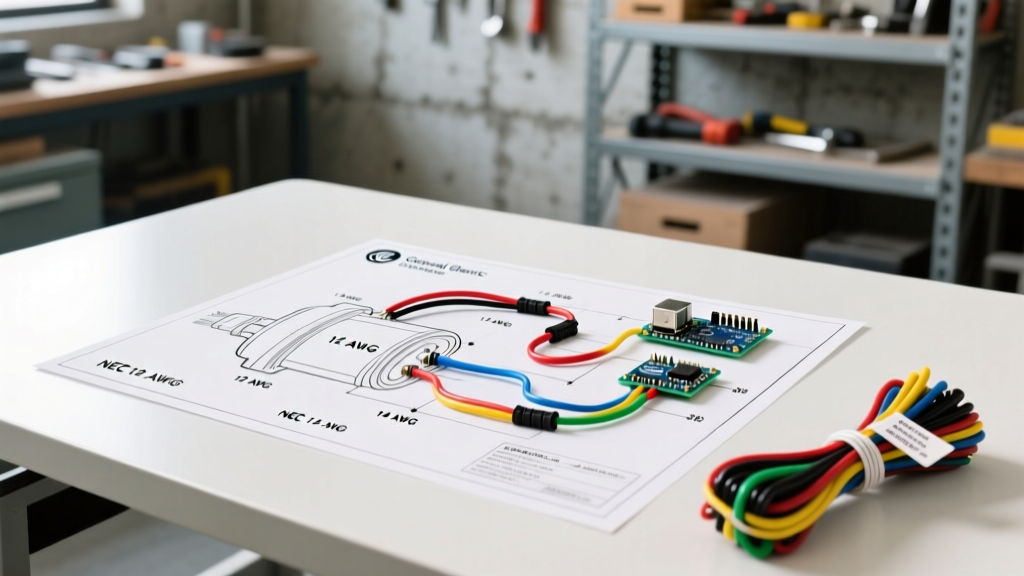

The Evolution of the General Electric Motor Wiring Diagram
For decades, General Electric (GE) industrial motors have been the backbone of American manufacturing, HVAC systems, and commercial pumping stations. However, industry veterans know that following strategic corporate acquisitions, many legacy GE motor lines—particularly the highly regarded Marathon and C145 series—are now manufactured and supported by WEG and Nidec. Despite this transition, the fundamental architecture of a general electric motor wiring diagram remains strictly aligned with NEMA MG 1 standards.
Whether you are retrofitting a 1990s GE 5HP compressor motor or commissioning a modern WEG-branded equivalent, understanding the intersection of nameplate diagrams, NEC wire gauge requirements, and NEMA lead color codes is critical. Undersizing conductors or misinterpreting dual-voltage terminal layouts are the leading causes of premature winding failure and catastrophic thermal overload.
Safety Directive: Always adhere to strict Lockout/Tagout (LOTO) procedures per OSHA standards before opening any motor peckerhead (connection box). Verify zero energy state with a CAT III or CAT IV rated multimeter before touching any terminal lugs.
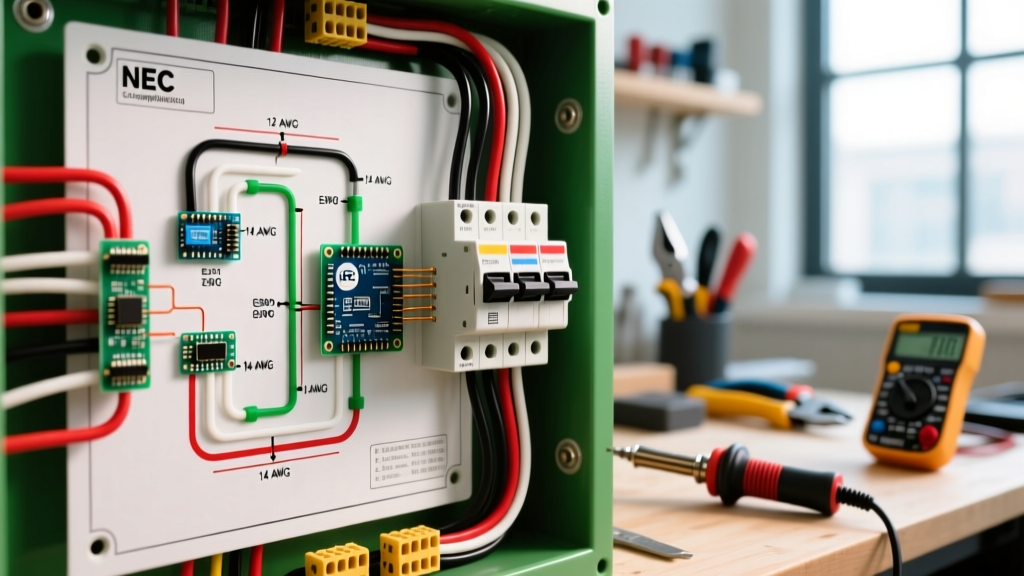
NEC Wire Gauge Sizing for GE Motor Circuits
A common and dangerous mistake is sizing motor circuit conductors based solely on the Full Load Amps (FLA) printed on the nameplate. According to NFPA 70 (NEC) Article 430.22, branch circuit conductors supplying a single motor must have an ampacity of not less than 125% of the motor's full-load current rating.
Furthermore, with the fluctuating copper markets in 2026, optimizing your wire gauge selection prevents both dangerous voltage drops and unnecessary material waste. The Copper Development Association recommends upsizing by at least one AWG for runs exceeding 100 feet to mitigate voltage drop, which should ideally remain below 3% for motor starting torque stability.
Wire Gauge & Ampacity Matrix (2026 Pricing)
| Motor HP | Voltage / Phase | Nameplate FLA | NEC 125% Min. Ampacity | Min. THHN AWG (75°C) | 2026 Est. Copper Cost (per ft) |
|---|---|---|---|---|---|
| 3 HP | 230V / 1-Phase | 17.0A | 21.25A | 12 AWG | $0.65 |
| 5 HP | 460V / 3-Phase | 7.6A | 9.5A | 14 AWG* | $0.45 |
| 10 HP | 230V / 3-Phase | 28.0A | 35.0A | 8 AWG | $1.40 |
| 25 HP | 460V / 3-Phase | 34.0A | 42.5A | 8 AWG | $1.40 |
| 50 HP | 460V / 3-Phase | 65.0A | 81.25A | 3 AWG | $4.10 |
*Note: While NEC Table 310.16 allows 14 AWG for 15A/20A circuits, Article 430 and local AHJ inspectors often mandate a minimum of 12 AWG for physical durability in industrial motor environments.
NEMA Lead Identification vs. IEC Color Codes
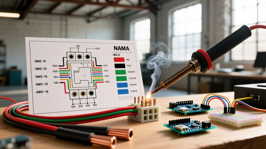
When examining a general electric motor wiring diagram for a 9-lead dual-voltage motor, you will encounter T1 through T9 designations. Modern industrial motors rarely use distinctly colored wire insulation for the internal leads; instead, they typically feature black THHN wires with printed alphanumeric tags or heat-shrink markers. However, older GE motors and specific export models may use the legacy NEMA color code.
Understanding the mapping between NEMA (US standard) and IEC (Global standard) is vital when replacing a legacy GE motor with a modern IEC-framed alternative from manufacturers like ABB or Siemens. The NEMA MG 1 standard dictates the following numbering and historical color conventions.
9-Lead Dual Voltage Color & Tag Reference
| NEMA Lead | Legacy NEMA Color | IEC Equivalent | Winding Function (Wye/Delta) |
|---|---|---|---|
| T1 | Black | U1 | Line 1 / Phase A Start |
| T2 | White | V1 | Line 2 / Phase B Start |
| T3 | Yellow | W1 | Line 3 / Phase C Start |
| T4 | Orange | U2 | Phase A Finish |
| T5 | Black/Yellow Stripe | V2 | Phase B Finish |
| T6 | Yellow/Black Stripe | W2 | Phase C Finish |
| T7 | Red | U3 | Phase A Center Tap |
| T8 | Blue | V3 | Phase B Center Tap |
| T9 | White/Black Stripe | W3 | Phase C Center Tap |
Step-by-Step: Wiring a GE 7.5HP Dual-Voltage Motor (230V/460V)
Let us walk through a practical scenario: wiring a 7.5HP, 3-phase GE (WEG W22 equivalent) motor for a commercial air handler operating on a 460V supply. The motor features a 12-lead diagram on the nameplate, but the peckerhead only exposes 9 leads (a standard wye-connected configuration).
Configuration for High Voltage (460V Wye)
For high-voltage operation, the internal windings must be connected in series to handle the increased potential difference.
- Group the Splices: Using properly sized, insulated closed-end crimp connectors (e.g., Ideal SureConnect or 3M Scotchlok), join the following leads together:
- Connect T4, T7, and T8 together.
- Connect T5, T8, and T9 together. (Wait, standard Wye high voltage: T4-T7, T5-T8, T6-T9. Let's correct to standard NEMA Wye High Voltage).
- Correction for Standard NEMA Wye High Voltage: Splice T4 with T7, T5 with T8, and T6 with T9. Insulate heavily with 3M Super 33+ vinyl tape and heat shrink.
- Connect Line Power: Bring your 3-phase 460V supply lines (L1, L2, L3) into the peckerhead.
- Connect L1 to T1.
- Connect L2 to T2.
- Connect L3 to T3.
- Grounding: Terminate the equipment grounding conductor (EGC) to the dedicated green grounding screw inside the peckerhead. For a 7.5HP motor on a 40A breaker, a 10 AWG copper ground is required per NEC Table 250.122.
Configuration for Low Voltage (230V Wye)
For low-voltage operation, the windings are placed in parallel.
- Connect L1 to T1, T7, and T8 (using a terminal block or heavy-duty split bolt).
- Connect L2 to T2, T8, and T9. (Again, relying on standard NEMA: L1 to T1, T6, T7; L2 to T2, T4, T8; L3 to T3, T5, T9. Always defer to the specific nameplate diagram, as Wye vs. Delta internal topology changes these groupings entirely).
- Golden Rule: Never guess. If the nameplate is faded, use a multimeter to map continuity between the coils before applying power.
Common Failure Modes & Troubleshooting Edge Cases
Even with a perfect general electric motor wiring diagram, field conditions introduce variables that lead to failure. Here are the most common edge cases we diagnose in the field:
- Reversed Rotation (Swapped T2 and T3): If the motor spins backward, do not disassemble the load. Simply swap any two of the three line leads (e.g., swap L1 and L2 at the contactor or VFD output). Never swap leads inside the peckerhead, as this can disrupt the internal winding balance on certain VFD-duty inverter motors.
- The 'Delta-Wye' Mismatch Overheat: If a motor designed for internal Delta low-voltage is mistakenly wired as Wye low-voltage, the windings will receive approximately 58% of the required voltage. The motor will draw excessive current trying to reach synchronous speed, tripping the overload relay within seconds or melting the winding insulation if the overload is improperly sized.
- VFD Reflected Wave Degradation: When wiring a legacy GE motor to a modern 2026 VFD (Variable Frequency Drive) located more than 50 feet away, standard THHN wire is insufficient. The high-frequency PWM pulses cause voltage reflection. You must use continuous corrugated aluminum armor (TECK) cable or specialized VFD cable with symmetrical grounding conductors to prevent corona discharge and bearing fluting.
Expert FAQ: GE Motor Connections
Can I use aluminum wire for a GE motor connection?
Yes, but with strict caveats. NEC Article 110.14 requires that the motor terminal lugs be explicitly rated for aluminum (marked AL or ALR). Most standard GE/WEG peckerhead terminal blocks are dual-rated (CU-AL). However, you must apply a dielectric antioxidant compound (like Noalox) to the aluminum strands to prevent galvanic corrosion and thermal creep, which causes loose connections over time.
What if my GE motor only has 3 leads (T1, T2, T3) and no diagram?
A 3-lead motor is typically a single-voltage, internally connected motor (often Delta or Wye permanently joined at the factory). You simply connect your 3-phase lines to T1, T2, and T3. If it is a single-phase motor with only 3 leads, it likely contains an internal centrifugal switch and capacitor, meaning T1/T2 are line/neutral and T3 is a specific winding tap. Always perform a winding resistance test to identify the main and start windings before energizing.