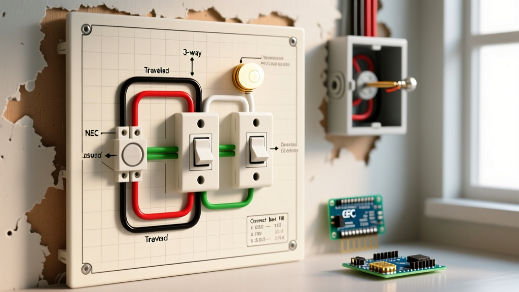

Understanding the Code-Compliant Wiring Diagram for 3 Way Switch with 2 Lights
Wiring a multi-location lighting circuit requires more than just connecting colored wires; it demands strict adherence to the National Electrical Code (NEC) to prevent arc faults, overheating, and fire hazards. When searching for a reliable wiring diagram for 3 way switch with 2 lights, many online tutorials ignore critical updates from the latest NEC cycles regarding neutral requirements and box fill calculations. This guide provides a comprehensive, safety-first approach to wiring two lights controlled by two 3-way switches, ensuring your installation passes inspection and operates safely for decades.
According to the National Fire Protection Association (NFPA) NEC 70, residential lighting circuits must be designed to accommodate future smart home technologies without requiring invasive rewiring. This fundamentally changes how we route cables between switch boxes compared to legacy methods.
The NEC 404.2(C) Mandate: Neutral at Every Switch Box
The most critical code update affecting 3-way switch diagrams is NEC Article 404.2(C). This rule mandates that a neutral conductor must be present at all switch locations controlling lighting loads. Why? Modern smart switches, occupancy sensors, and Wi-Fi-enabled dimmers require a continuous 120V neutral path to power their internal electronics. If you wire a 3-way circuit using the old 'dead-end traveler' method, you will fail inspection and prevent the future use of smart lighting.
How This Affects Your Cable Routing
In a standard 3-way setup with two lights, power typically enters the first switch box. To comply with the neutral mandate:
- Switch Box 1 (Line Side): Receives 14/2 NM-B (Line, Neutral, Ground) from the breaker panel. The neutral must be pigtailed and capped here, even if not used by a standard toggle switch.
- Between Switch 1 and Switch 2: You must carry two travelers, the line (or switched line), a neutral, and a ground. Standard 14/3 cable only provides three current-carrying conductors. To meet code, professional electricians either use expensive 14/4 NM-B cable or, more commonly, run a 14/3 cable (for travelers and line) alongside a separate 14/2 cable (dedicated solely to extending the neutral to Box 2).
- Switch Box 2 (Load Side): Receives the travelers, line, and neutral. The switched load (14/2) then exits this box to feed Light 1, which subsequently daisy-chains to Light 2.
Expert Safety Warning: Never use a ground wire as a substitute for a neutral conductor. This creates a severe shock hazard and will immediately trip a modern AFCI/GFCI breaker. Always refer to OSHA Electrical Safety Guidelines when working on live panels or verifying ground paths.
Component Specifications and Material Selection
Using commercial-grade components ensures longevity and secure terminations. Below is the recommended bill of materials for a standard 15-Amp residential lighting circuit.
| Component | Specification / Model | Code / Safety Rationale |
|---|---|---|
| Circuit Breaker | 15A AFCI (Arc Fault) | NEC 210.12 requires AFCI protection for all bedroom and living area branch circuits. |
| Wire (Branch) | 14/2 NM-B (Romex) | Rated for 15A. Must have 90°C THHN conductors inside the sheath. |
| Wire (Travelers) | 14/3 NM-B + 14/2 NM-B | 14/3 for travelers/line; parallel 14/2 to satisfy NEC 404.2(C) neutral requirement. |
| Switches | Leviton Decora 5603-2W | Commercial spec grade, side-wire backwire clamps for superior grip over push-in stab connections. |
| Wire Connectors | WAGO 221 Series Lever Nuts | UL-listed, transparent housing for visual inspection, handles up to 5 solid 14 AWG wires securely. |
| Electrical Boxes | Carlon B618R-UPC (22 cu in) | Oversized single-gang boxes required to meet NEC 314.16 box fill calculations. |
Box Fill Calculations: Avoiding Overcrowding (NEC 314.16)
One of the most frequent reasons electrical inspectors fail 3-way switch installations is box overcrowding. NEC Article 314.16 dictates the minimum cubic inch (cu in) volume required based on the number and gauge of conductors entering the box.
Calculating Switch Box 1 (Line Side)
Let us calculate the exact box fill for the first switch box, assuming 14 AWG wire (which requires 2.0 cu in per conductor volume allowance):
- 14/2 from Panel: 2 conductors (Line, Neutral) = 4.0 cu in
- 14/3 to Switch 2: 3 conductors (Line, Traveler 1, Traveler 2) = 6.0 cu in
- 14/2 to Switch 2 (Neutral Bypass): 1 conductor (Neutral) = 2.0 cu in
- Switch Yoke: Counts as 2 conductors based on the largest wire connected = 4.0 cu in
- Ground Wires: All grounds combined count as 1 conductor = 2.0 cu in
- Clamps: Internal plastic clamps count as 1 conductor = 2.0 cu in
Total Minimum Volume Required: 20.0 cubic inches. A standard 'old work' single-gang box is typically 14 to 18 cubic inches, which is a direct code violation for this setup. You must use a deep 22 cu in box or a double-gang box with a single-gang mud ring.
Step-by-Step Code-Compliant Wiring Execution
Before beginning, ensure the main breaker is OFF and verify zero voltage using a non-contact tester and a multimeter. The U.S. Consumer Product Safety Commission (CPSC) emphasizes that verifying a de-energized state with a calibrated meter is the single most important safety step in DIY electrical work.
Phase 1: Prepping the Conductors
Strip exactly 3/4 inch of insulation from all 14 AWG solid copper wires. Stripping too little leaves exposed copper outside the wire nut or lever nut; stripping too much risks a short circuit inside the crowded box. Use precision wire strippers like the Klein Tools 11063W to avoid nicking the copper, which creates a weak point that can snap during box folding.
Phase 2: Wiring Switch Box 1 (Line Side)
- Grounds: Connect all bare copper ground wires together with a WAGO 221 lever nut. Run a 6-inch bare copper pigtail to the green ground screw on the 3-way switch.
- Neutrals: Connect the white neutral from the panel, the white neutral from the 14/2 bypass cable heading to Switch 2, and a white pigtail. Cap them securely. Do not connect the neutral to the standard 3-way switch.
- Line (Hot): Connect the black wire from the panel to the black 'Common' (or Line) terminal screw on the 3-way switch. Tighten to the manufacturer's torque specification (usually around 14 in-lbs).
- Travelers: Connect the red and black wires of the 14/3 cable to the two brass traveler terminal screws on the switch. The order does not matter for standard 3-way operation.
Phase 3: Wiring Switch Box 2 (Load Side)
- Grounds & Neutrals: Bond all grounds together and pigtail to the switch. Bond the incoming white neutral from the 14/2 bypass cable to the white neutral of the 14/2 cable heading to Light 1.
- Travelers & Line: Connect the red and black wires from the incoming 14/3 cable to the brass traveler screws. Connect the white wire from the 14/3 cable (which is acting as the hot line feed from Switch 1; ensure it is re-identified with black electrical tape at both ends per NEC 200.7) to the black Common terminal on Switch 2.
- Switched Load: Connect the black wire of the 14/2 cable heading to Light 1 to the remaining terminal on Switch 2 (often marked as the load or secondary common, depending on the switch brand topology).
Phase 4: Daisy-Chaining the Lights
At Light 1, connect the incoming black (switched hot) to the black fixture wire, and the incoming white to the white fixture wire. Run a new 14/2 cable from Light 1 to Light 2, connecting black-to-black and white-to-white using wire nuts. Bond all ground wires to the metal junction box (if metal) and the fixture's ground pigtail.
Common Code Violations and Troubleshooting
Even with a perfect diagram, execution errors can cause failures. Here are the most common issues encountered during inspections and how to resolve them:
- Violation: Re-identified Conductors Missing Tape. When using the white wire in a 14/3 cable as a hot traveler or line feed, NEC 200.7(C)(2) requires it to be permanently re-identified with black or red tape at every termination point. Failing to do so is an automatic inspection fail.
- Violation: Bootleg Neutrals. Some DIYers attempt to grab a neutral from a completely different circuit (e.g., a nearby receptacle) to power a smart switch. This causes current to flow on the ground wire of the lighting circuit, tripping AFCI breakers and creating a fire hazard.
- Troubleshooting: Lights Flicker on LED Bulbs. If your LED lights flicker when off, it is often due to induced voltage on long traveler runs. Install an Lutron LUT-MLC (MLC-1) capacitor across the load at the first light fixture to bleed off ghost voltage.
Frequently Asked Questions (FAQ)
Can I use 12 AWG wire instead of 14 AWG for this diagram?
Yes, you can always use a larger wire gauge than required. If your circuit is protected by a 20-Amp breaker, you must use 12 AWG wire exclusively. Never mix 14 AWG and 12 AWG wire on the same 20-Amp circuit, as the 14 AWG wire could overheat and melt before the breaker trips.
Do I need a special switch for LED lighting?
Standard mechanical 3-way switches (like the Leviton 5603) work perfectly with LED bulbs. However, if you are installing a 3-way dimmer, you must purchase a dimmer specifically rated for LED loads (such as the Lutron Diva DVCL-153P) to prevent flickering and premature driver failure.
What if my house wiring has no ground wire?
If you are working in an older home with ungrounded (2-wire) knob-and-tube or early Romex, NEC 404.9(B) allows you to install a 3-way switch without a ground connection, provided you use a non-metallic (plastic) faceplate. However, upgrading the circuit to include a proper equipment grounding conductor is highly recommended for safety.