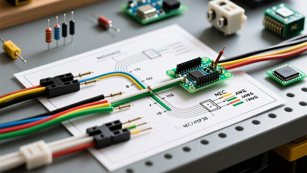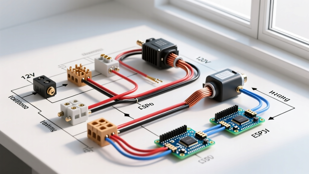

The Critical Intersection of Electric Window Wiring and Safety Compliance
Whether you are retrofitting a classic car with an aftermarket 12V DC power window kit or installing a 120V AC automated window actuator for residential ventilation, understanding the underlying electric window wiring diagram is only half the battle. The other half—and arguably the more important one—is ensuring your installation adheres to modern safety standards and electrical codes. A poorly wired window motor doesn't just risk blowing a fuse; it introduces severe fire hazards from thermal runaway and catastrophic pinch-point injuries.
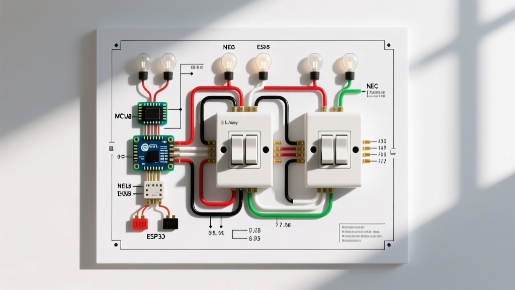
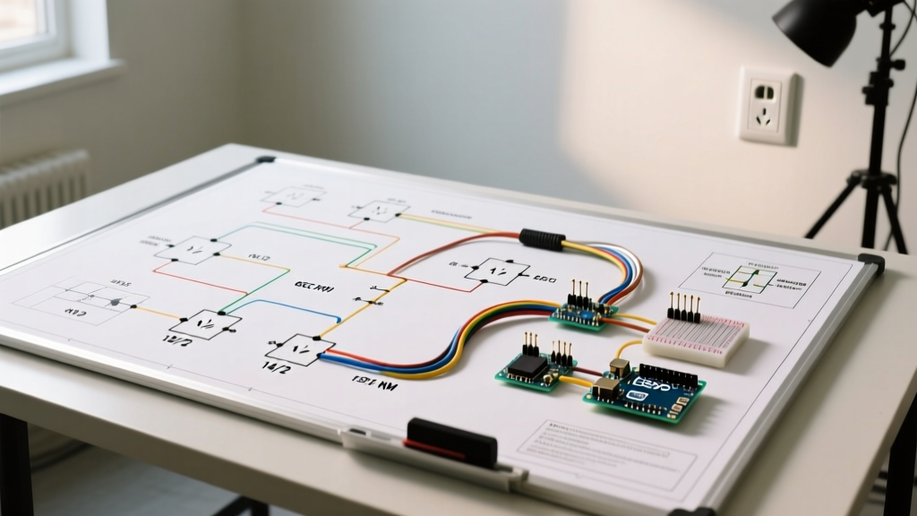
In this comprehensive guide, we dissect the wiring architectures for both automotive and residential electric windows. We will cover exact wire gauge requirements, relay H-bridge logic, and the specific National Electrical Code (NEC) and Federal Motor Vehicle Safety Standards (FMVSS) that govern these circuits in 2026.
Core Safety Principles for Electric Window Circuits
Electric window motors are high-torque, reversible DC or AC motors that draw massive inrush currents. When a window reaches the end of its travel, the motor stalls, causing amperage to spike dramatically. If the circuit is not properly protected, this stall current will melt wire insulation and ignite surrounding materials.
- Overcurrent Protection: Every window circuit must have a dedicated fuse or circuit breaker sized to the wire's ampacity, not just the motor's running current.
- Relay Isolation: Switches should never carry the full motor load. They must only trigger low-amperage relay coils, keeping high-current paths isolated and minimizing voltage drop.
- Thermal Overload: Residential AC actuators must feature internal thermal cutoffs or external overload relays to prevent fires during a mechanical jam.
12V DC Automotive Power Window Wiring Diagram Breakdown
Aftermarket automotive power window kits (such as those from Electric Life or Autoloc) typically utilize a dual 5-pin SPDT (Single Pole Double Throw) relay setup to create an H-Bridge. This allows a standard 3-position toggle switch to reverse the polarity of the 12V DC motor safely.
Wire Gauge and Fusing Matrix
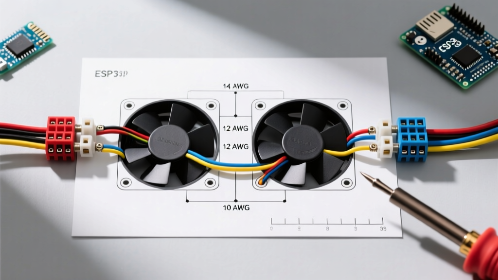
Selecting the correct wire gauge is dictated by the maximum stall current of the motor and the length of the wire run. Standard automotive window motors draw 15A–20A under load, but stall currents can reach 35A–40A.
| Wire Gauge (AWG) | Max Ampacity (Chassis) | Recommended Fuse Size | Application Scenario |
|---|---|---|---|
| 14 AWG | 32A | 25A MAXI | Small coupe doors, short runs (<10 ft) |
| 12 AWG | 41A | 30A MAXI | Standard sedans, heavy-duty truck windows |
| 10 AWG | 55A | 40A MAXI | Limousines, multi-window centralized feeds |
| 18 AWG | 10A | 5A Mini | Switch control wires (Relay coils 85/86) |
Note: Always use SAE J1128 compliant primary wire for automotive applications to ensure the insulation can withstand under-door heat and moisture.
Step-by-Step: Wiring the 5-Pin SPDT Relay H-Bridge
The most common failure point in DIY electric window wiring diagrams is miswiring the relay H-bridge. Using two standard Bosch-style 5-pin relays (Terminals: 30, 87, 87a, 85, 86), follow this exact pinout to ensure safe polarity reversal without creating a dead short.
- Power Feed (Terminal 30): Run a fused 12AWG wire directly from the vehicle's main 12V distribution block to Terminal 30 on both relays. Do not daisy-chain power from the ignition switch; window motors require constant or accessory-switched high-amperage feeds.
- Ground Path (Terminal 87a): Tie Terminal 87a on both relays together and route them to a clean, bare-metal chassis ground using a ring terminal and star washer.
- Motor Leads (Terminal 87): Connect Terminal 87 of Relay A to Motor Wire 1. Connect Terminal 87 of Relay B to Motor Wire 2.
- Switch Control (Terminals 85 & 86): Connect Terminal 86 on both relays to a 12V ignition-switched source. Connect Terminal 85 of Relay A to the 'UP' terminal on your rocker switch, and Terminal 85 of Relay B to the 'DOWN' terminal.
CRITICAL SAFETY WARNING: Never wire the window switch directly to the motor without relays. Standard OEM-style rocker switches are rated for 10A-15A max. Routing 30A stall currents through the switch will melt the internal copper contacts, potentially fusing the switch in the 'ON' position and causing the motor to burn out or catch fire.
120V AC Residential Electric Window Actuator Wiring
Residential electric window openers (chain or linear actuators) used for smart home ventilation or smoke extraction operate on entirely different principles and are governed by the National Electrical Code (NEC). In 2026, inspectors are heavily scrutinizing motorized window installations for compliance with NEC Article 430 (Motors and Motor Controllers) and Article 210.8 (GFCI Protection).
NEC Compliance Checklist for Home Actuators
- GFCI Protection: Because window actuators are installed near the exterior envelope where condensation or rain ingress can occur, any 120V AC receptacle or hardwired branch circuit within 6 feet of the window sill must be GFCI protected per NEC 210.8.
- Overload Protection: Per NFPA 70 (NEC) Article 430.32, continuous-duty motors must have separate overload protection. Ensure your smart actuator controller (like the Shelly Plus 1PM or a dedicated Somfy controller) has built-in thermal monitoring and automatic shutoff.
- Low-Voltage Control Isolation: If you are using a 24V DC actuator with a smart home relay, the 120V AC transformer must be housed in a UL-listed junction box, and the 24V DC control wires must be routed separately from the line-voltage wires to prevent inductive interference and shock hazards.
Entrapment Protection and Anti-Pinch Standards
Wiring the motor correctly is meaningless if the system lacks entrapment protection. The physics of a window motor can exert over 100 pounds of upward force—enough to cause severe injury or asphyxiation.
For automotive applications, the NHTSA FMVSS 118 standard mandates that power windows must not close automatically unless the vehicle is in the 'ON' or 'ACCESSORY' position, or if equipped with an auto-reverse sensor that stops and reverses the window upon encountering 20 Newtons of resistance. When wiring an aftermarket 'Express-Up' module, you must integrate the OEM Hall-effect pinch sensor. Bypassing this sensor to simplify the wiring diagram is a massive liability and safety violation.
For residential and commercial buildings, automated windows used for natural ventilation must comply with UL 325 standards regarding entrapment. This usually requires wiring a secondary edge-sensor mat or an optical beam across the window frame that cuts power to the actuator's closing circuit immediately upon beam interruption.
Common Failure Modes & Troubleshooting
Even with a perfect schematic, real-world variables introduce faults. Here is how to diagnose the most common issues safely:
1. Voltage Drop Under Load
Symptom: The window moves slowly or stops halfway, but the motor hums. Testing with a multimeter at the battery shows 12.6V, but testing at the motor terminals while actuating shows only 9.5V.
Diagnosis: This is almost always caused by undersized wire or poor ground connections. The high resistance causes voltage to drop as heat. Check the chassis ground for paint or rust, and verify your wire gauge matches the run length. Use a voltage drop test across the fuse, the relay terminals, and the ground strap.
2. Relay Contact Welding
Symptom: The window continues to push against the top seal even after releasing the switch, eventually tripping the main fuse or burning the motor.
Diagnosis: The internal contacts of the SPDT relay have arced and welded together due to repeated high-amperage stall events. Safety Action: Immediately disconnect the battery. Replace the relays with high-quality, sealed units from reputable manufacturers like Littelfuse or Hella. Never use cheap, unbranded relays for inductive motor loads.
3. Smart Home Actuator Wi-Fi Desync & Safety Override
Symptom: A 120V smart window actuator fails to close during a rainstorm because the local Wi-Fi network dropped.
Diagnosis: Relying solely on cloud-based control for environmental sealing is a critical design flaw. Always wire a local, hardwired manual override switch in parallel with the smart relay. Ensure the local switch is a 'maintained' or 'momentary' type that physically overrides the smart relay's logic board, allowing you to secure the home envelope during network outages.
Final Thoughts on Code-Compliant Wiring
An electric window wiring diagram is a blueprint, but safety and code compliance dictate the reality of the installation. Whether you are crimping 12 AWG wires for a classic car restoration or terminating 120V AC lines for a smart-home skylight actuator, prioritize overcurrent protection, relay isolation, and entrapment sensors. By adhering to FMVSS and NEC guidelines, you ensure your automated windows provide convenience without compromising the safety of the vehicle's occupants or the home's residents.