
Understanding the Topology: Power-to-Switch vs. Power-to-Light
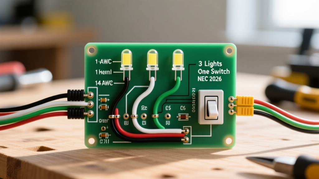
When planning a wiring diagram for 3 lights one switch, the physical layout of your cable runs dictates your material list, wire gauge, and color code application. In residential and commercial lighting, there are two primary topologies for daisy-chaining multiple fixtures to a single single-pole switch. Choosing the right one is critical for meeting modern electrical codes and ensuring future compatibility with smart home devices.
Topology A: Power Source to Switch First (Preferred)
In this layout, the main power feed (from the breaker panel) enters the switch box first. From the switch, a single 2-wire cable runs to Light 1, then continues to Light 2, and finally terminates at Light 3.
- Cable Required: 14/2 or 12/2 NM-B (Romex) for the entire run.
- Advantage: The switch box inherently contains the neutral wire, making it instantly compatible with smart switches, timers, and motion sensors without code violations.
Topology B: Power Source to Light First (The Switch Loop)
Here, power hits the ceiling junction box of Light 1 first. A cable must then be dropped down to the wall switch. Historically, electricians used 14/2 cable for this 'switch loop,' using the white wire as a hot feed and the black as the switched return. This is no longer code-compliant.
NEC 404.2(C) Requirement: Modern National Electrical Code (NEC) mandates that a neutral conductor must be present at the switch box. If power hits the light first, you must use 14/3 or 12/3 cable (Black, Red, White, Bare) to drop down to the switch, reserving the white wire strictly for the neutral and using black/red for the hot loop.
Wire Gauge Selection: 14 AWG vs. 12 AWG
Wire gauge is determined by the overcurrent protection device (breaker) protecting the circuit, not merely the wattage of the three lights. While three LED fixtures might only draw 0.5 amps combined, the circuit must be wired to handle the breaker's maximum rating to prevent a fire hazard in the event of a short circuit.
| Breaker Size | Minimum Wire Gauge | Cable Type (NM-B) | NEC Box Fill Volume (per wire) | Max Circuit Wattage (120V) |
|---|---|---|---|---|
| 15 Amp | 14 AWG | 14/2 or 14/3 | 2.0 cubic inches | 1,440W (Continuous: 1,152W) |
| 20 Amp | 12 AWG | 12/2 or 12/3 | 2.25 cubic inches | 1,920W (Continuous: 1,536W) |
Pro-Tip for Box Sizing: When wiring Light 1 in a daisy-chain, the junction box acts as a splice point. It will contain the power-in, power-out to Light 2, and the switch loop. According to NFPA 70 National Electrical Code Article 314, you must calculate box fill carefully. For a 14 AWG circuit with 4 cables entering the box (8 current-carrying conductors, plus grounds and clamps), you need a minimum of an 18-cubic-inch 'deep' octagonal or round pan box. Standard 12-cubic-inch shallow boxes will result in a failed inspection and crushed wires.
Voltage Drop: The Hidden Killer of Multi-Light Runs
When wiring three lights in series (electrically parallel, but physically daisy-chained), the cumulative length of the wire increases resistance. If the distance from the breaker to Light 3 exceeds recommended limits, the third fixture will suffer from voltage drop, resulting in dimming or premature LED driver failure.
The NEC recommends a maximum 3% voltage drop on branch circuits for optimal efficiency. Below are the maximum one-way run lengths from the breaker to the third light fixture, assuming a conservative 10A load (to account for future circuit expansions).
| Wire Gauge | Max Run Length (3% Drop at 120V / 10A) | Max Run Length (3% Drop at 120V / 2A LED Load) |
|---|---|---|
| 14 AWG Copper | 58 feet | 290 feet |
| 12 AWG Copper | 92 feet | 460 feet |
If your three lights are spread across a long driveway, a large warehouse, or an extended hallway exceeding 60 feet on a 14 AWG circuit, you must upsize to 12 AWG wire or run a dedicated home-run cable to Light 3 to maintain proper voltage. You can verify specific project metrics using the Southwire Voltage Drop Calculator.
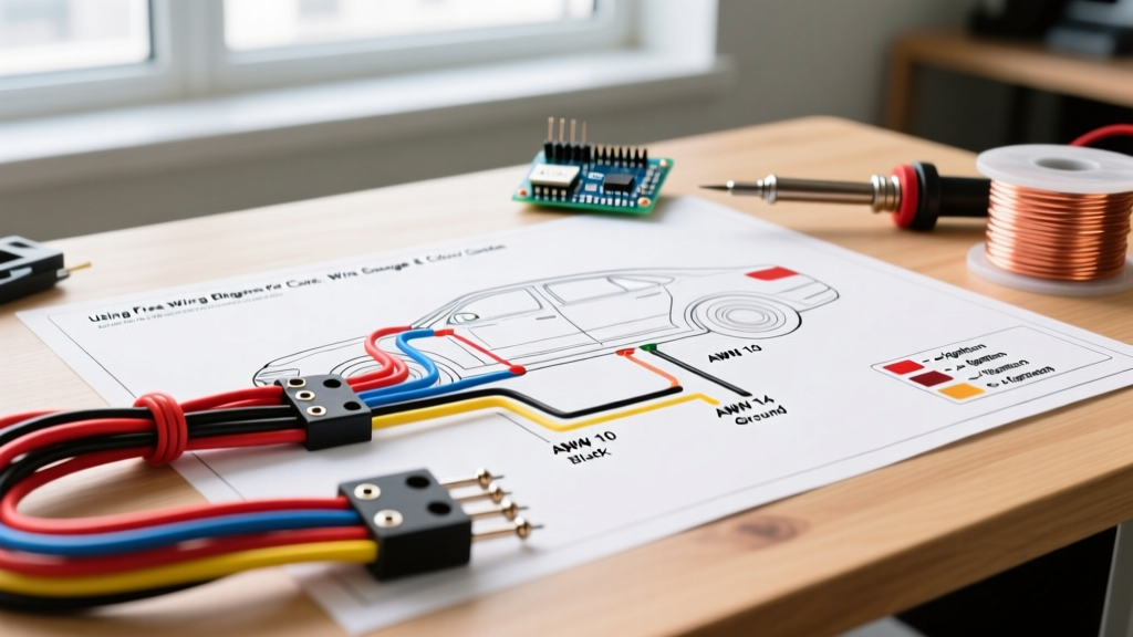
2026 NEC Color Code Standards & Re-Identification
Adhering to strict color codes prevents fatal shocks during future maintenance. In a standard 120V AC single-phase system, the insulation colors are non-negotiable:
- Black / Red / Blue: Ungrounded (Hot) conductors. Used for the constant hot feed and the switched-hot return to the lights.
- White / Gray: Grounded (Neutral) conductor. Must never be used as a hot wire unless permanently re-identified.
- Bare Copper / Green: Equipment Grounding Conductor (EGC).
The Re-Identification Rule (NEC 200.7)
If you are forced to use a white wire as a hot conductor (e.g., in older switch loop retrofits where 14/3 wasn't pulled), the NEC requires you to permanently re-identify the white wire at both ends using black electrical tape or permanent marker. However, as of the 2026 code cycle, inspectors are heavily penalizing the use of 14/2 for switch loops. Always pull 14/3 for switch drops to keep the white wire purely neutral and use the red wire as the switched-hot return.
Step-by-Step Wiring & Pro-Tips for Daisy Chaining
- Shut Off and Verify: Turn off the 15A or 20A breaker. Use a non-contact voltage tester (NCVT) and a multimeter to confirm zero voltage at the splice points.
- Strip with Precision: Strip exactly 3/4 inch of insulation from the NM-B wires. Scoring the copper conductor with wire strippers creates a weak point that can snap inside the wire nut, causing an arc fault.
- Use Lever Connectors for Splices: When daisy-chaining Light 1 and Light 2, you are often joining 4 or 5 wires together (Line-in, Line-out, Switched-hot, Neutrals). Traditional twist-on wire nuts become unreliable and physically bulky with five 14 AWG wires. Instead, use Wago 221-415 (5-port) lever nuts. They cost roughly $0.55 each, require no twisting force, provide a transparent housing for visual inspection, and guarantee a gas-tight connection.
- Ground Pigtailing: Never daisy-chain the ground wire by simply looping it from one cable to the next through the fixture's green ground screw. Use a copper crimp sleeve or a Wago 221 to pigtail the incoming grounds, outgoing grounds, and the fixture's ground wire together, then run a single pigtail to the metal junction box and fixture.
Troubleshooting Edge Cases in 3-Light Runs
LED Ghosting and Flickering
If your three lights are low-wattage LEDs and you notice a faint glow when the switch is off, you are likely experiencing induced voltage or capacitance on long parallel wire runs. This is common in Topology B when 14/3 cable is run over long distances alongside other active circuits. Fix: Install a dummy load resistor (like the Lutron LUT-MLC) across the hot and neutral at Light 3 to bleed off the phantom voltage.
Dimming at the Third Fixture
If Light 3 is visibly dimmer than Light 1, you have a high-resistance connection or severe voltage drop. First, check the Wago connectors or wire nuts at Light 2; a loose neutral will cause a voltage imbalance. If connections are tight, measure the voltage at Light 3 with a multimeter while the circuit is under load. If it reads below 114V on a 120V system, you must upsize the feed wire to 12 AWG or 10 AWG to combat resistance over distance.
By combining the correct topology, strict adherence to NEC color codes, and precise wire gauge calculations, your 3-light installation will be safe, code-compliant, and ready for the next generation of smart lighting controls.