
Understanding the SAE J560 Standard for Heavy-Duty Trailers
When working on commercial motor vehicles, relying on generic RV wiring diagrams is a critical mistake that leads to DOT violations and catastrophic electrical failures. The definitive standard for heavy-duty truck and trailer electrical connections in North America is SAE J560. This standard dictates the physical dimensions, pin assignments, and wire gauge requirements for the ubiquitous 7-way blade connector found on semi-trailers, flatbeds, and heavy equipment transports.
As we move through 2026, the rapid industry shift toward all-LED trailer lighting and advanced ABS/EBS (Anti-lock/Electronic Braking Systems) has fundamentally changed the electrical load profile of modern trailers. While LEDs draw significantly less amperage than legacy incandescent bulbs, they are hyper-sensitive to voltage drops and ground-loop interference. This comprehensive motor wiring tutorial will break down the exact SAE J560 wiring diagram, material specifications, and termination techniques required to build a bulletproof semi-trailer lighting harness.
The SAE J560 7-Way Pinout Matrix
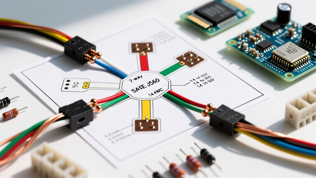
The 7-way connector utilizes a specific pin-and-color code. Deviating from this color code is not only a violation of federal regulations but creates severe safety hazards for technicians troubleshooting the rig on the side of a highway. Below is the exact pinout matrix required for commercial compliance.
| Pin | Wire Color | Function / Circuit | Min. Wire Gauge | Typical Load (LED) |
|---|---|---|---|---|
| 1 (Center) | White | Ground Return / Chassis | 10 AWG (or 8 AWG) | N/A |
| 2 | Black | Clearance, Side Marker, ID Lamps | 12 AWG | 2A - 4A |
| 3 | Yellow | Left Turn Signal & Stop Lamps | 12 AWG | 3A - 5A |
| 4 | Red | Auxiliary Power / ABS / EBS | 10 AWG | 10A - 15A (Peak) |
| 5 | Green | Right Turn Signal & Stop Lamps | 12 AWG | 3A - 5A |
| 6 | Brown | Tail Lamps, License Plate Lamp | 12 AWG | 2A - 4A |
| 7 | Blue | Auxiliary / Liftgate Power | 10 AWG | Varies |
Why Pin 1 and Pin 4 Demand Heavier Gauge Wire
Notice that Pins 1, 4, and 7 require 10 AWG (or thicker) wire. Pin 1 is the master ground return for the entire trailer lighting system. If you undersize this ground wire to 12 AWG, the cumulative amperage of the clearance, tail, and turn signals will cause a severe voltage drop. Pin 4 feeds the trailer's ABS/EBS module, which requires a massive transient current spike upon initial ignition. A voltage drop on Pin 4 will cause the trailer ABS to fault out, triggering a dashboard warning and an immediate out-of-service (OOS) violation during a DOT weigh station inspection.
Material Selection: SXL vs. Standard Automotive Wire
One of the most common failure points in DIY or budget-fleet trailer wiring is the use of GPT (General Purpose Thermoplastic) or THHN wire. These insulation types are entirely unsuited for the harsh undercarriage environment of a semi-trailer.
- GPT (PVC Insulation): Rated to 85°C. Becomes brittle in sub-zero temperatures and melts or shrinks back when exposed to high ambient heat near axles or brake drums.
- SXL (Standard Cross-Linked Polyethylene): Rated to 125°C. Highly resistant to road salts, diesel fuel, grease, and extreme thermal cycling. This is the mandated wire type for heavy-duty OEM harnesses.
- GXL / TXL: Also cross-linked and rated to 125°C, but with thinner insulation walls to save weight and allow for tighter bending radii in looms.
Pro Tip: In 2026, a 500-foot spool of 12 AWG SXL wire costs approximately $140 to $180. While it is a 30% premium over standard PVC automotive wire, the cost of a single roadside DOT fine ($250+) or a missed delivery due to lighting faults makes SXL the only logical choice.
Step-by-Step Termination and Crimping Protocol
The physical connection at the 7-way plug (such as the industry-standard Pollak 7-Pole HD, part #7-7001) is where moisture intrusion destroys harnesses. Follow this exact termination sequence:
- Strip the Jacket: Remove exactly 1/4 inch of insulation. Do not nick the copper strands; even a 10% reduction in cross-sectional copper area creates a localized hot spot.
- Select the Terminal: Use solid brass, nickel-plated terminals. Avoid stamped steel terminals which corrode rapidly.
- Hex-Crimp, Do Not Indent: Use a ratcheting hex-crimp tool (e.g., TE Connectivity or Ancor). An indent crimp leaves air pockets inside the terminal barrel. A hex crimp deforms the barrel uniformly, creating a gas-tight, cold-weld seal that prevents oxygen and moisture from reaching the copper.
- Dual-Wall Heat Shrink: Slide a piece of marine-grade, adhesive-lined heat shrink over the joint before crimping. After crimping, apply heat from the center outward until the adhesive sealant purges slightly from the edges. This completely waterproofs the connection.
Chassis Grounding: Bypassing the Hinge
Never rely on the trailer's mechanical hinges, pivot points, or fifth-wheel coupling as a ground return path. Paint, grease, and rust act as insulators. You must run a dedicated 10 AWG (or 8 AWG) white ground wire directly from the trailer's main lighting harness ground bus, securely bolted to a bare, sanded section of the trailer chassis, straight to Pin 1 on the 7-way plug.
Troubleshooting: The LED 'Ghosting' Phenomenon
A frequent complaint in modern retrofitted trailers is 'ghosting' or 'bleed-over'—where the left turn signal flashes, but the right clearance lights also pulse dimly. This is not a short circuit; it is a ground-loop issue exacerbated by LED technology.
Diagnostic Insight: LEDs require a minimum forward voltage to illuminate, but they are highly sensitive to micro-currents. If the main Pin 1 ground has high resistance (e.g., 3 ohms due to corrosion), the return current from the left turn signal will seek the path of least resistance back to the truck. It will backfeed through the clearance light circuit (Pin 2), illuminating the clearance LEDs dimly. The fix is never to add resistors; the fix is to repair the Pin 1 ground connection and verify it measures less than 0.2 ohms of resistance to the chassis.
Federal Compliance and DOT Inspection Readiness
According to 49 CFR § 393.9 and the broader FMVSS 108 standards enforced by the DOT, all commercial motor vehicles must maintain specific lighting configurations. Wiring a semi-trailer incorrectly doesn't just risk a blown fuse; it risks impoundment. Inspectors specifically look for:
- Proper Circuit Isolation: Turn signals must not illuminate the tail lamps, and brake lights must not trigger the clearance markers. (A common flaw when adapting European 13-pin ISO 11446 wiring diagrams to US 7-way SAE J560 systems without proper converter relays).
- Wire Loom Protection: Wires routed along the trailer sub-frame must be encased in split-loom tubing or braided nylon sleeves and secured with UV-rated cable ties every 18 inches to prevent chafing against the steel frame.
- Absence of 'Scotch-Loks': Piercing-type T-tap connectors are an immediate red flag for inspectors and a guaranteed failure point. All splices must be made using sealed, adhesive-lined butt connectors or solder-seal terminals.
Frequently Asked Questions (FAQ)
Can I use a standard RV 7-way diagram for a semi-trailer?
No. While both use 7 pins, the standard RV (SAE J286) pinout places the 12V auxiliary power on Pin 4 and the electric brakes on Pin 2. The heavy-duty SAE J560 standard places ABS power on Pin 4 and clearance lights on Pin 2. Cross-wiring an RV plug into a semi-trailer will instantly fry the trailer's ABS module or blow the truck's lighting fuse.
What is the maximum allowable voltage drop on a trailer lighting circuit?
For a 12V nominal system, the maximum allowable voltage drop from the truck's battery to the furthest trailer lamp is 0.5 volts (approx 4%). If your multimeter reads 12.6V at the truck's 7-way socket but only 11.2V at the rear trailer clearance light, you have an undersized wire, a corroded splice, or a failing ground that must be corrected before the trailer is dispatched.