
The Diagnostic Power of the Pioneer Wiring Diagram
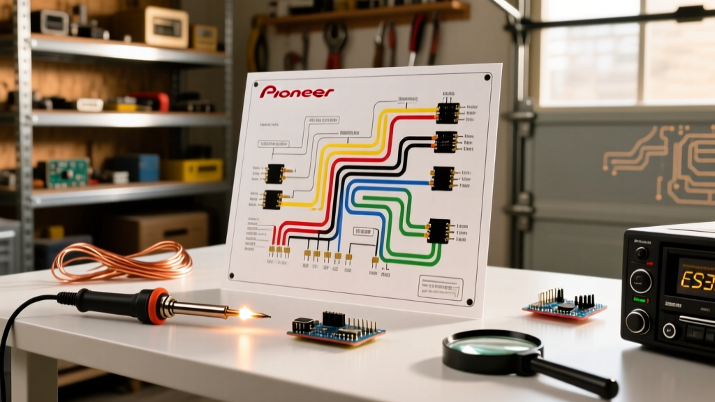
Installing an aftermarket head unit like the Pioneer DMH-W466NEX or AVH-W4500NEX is usually a straightforward process, but when the screen stays black or the speakers remain silent, guessing is not an option. A wiring diagram for Pioneer car radio systems is your primary diagnostic map. Unlike generic vehicle wiring charts, the manufacturer-specific diagram details the exact pinout, voltage requirements, and logic triggers required by Pioneer’s internal circuitry.
In 2026, with the proliferation of CAN-bus networks in late-model EVs and modern trucks, the physical wiring harness has evolved. However, the fundamental 16-pin or 18-pin Pioneer standard remains the backbone of power delivery and audio output. This guide moves beyond basic installation and focuses entirely on troubleshooting—using the wiring diagram to isolate failures, verify voltage drops, and protect your equipment from catastrophic shorts.
The Standard Pioneer 16-Pin Harness Matrix
Before grabbing a multimeter, you must understand the baseline architecture. Below is the diagnostic matrix for the standard Pioneer 16-pin power and speaker harness. Keep this referenced while probing your vehicle's adapter harness.
| Wire Color | Function | Target Voltage / Spec | Common Failure Mode if Incorrect |
|---|---|---|---|
| Yellow | B+1 (Constant 12V Memory) | 11.5V - 14.4V DC (Always On) | Radio resets presets; high parasitic drain if swapped. |
| Red | ACC (Switched 12V Ignition) | 0V (Off) / 12V (On) | Unit won't turn on, or stays on and kills battery. |
| Black | Chassis Ground | 0V (Max 0.2V drop under load) | Unit reboots during bass hits; screen flickers. |
| Blue/White | System Remote Control (Amp) | 12V Output (Max 300mA) | External amp stays on; head unit blows internal fuse. |
| Blue | Power Antenna Trigger | 12V Output (Radio/Tuner only) | Antenna stays up during CD/Bluetooth playback. |
| White / White-Black | Front Left Speaker (+/-) | AC Audio Signal (Class-D PWM) | Protection mode triggered if shorted to ground. |
Decoding the Diagram: 3 Common Pioneer Install Failures
Failure 1: The 'Memory Loss' and No-Power Dilemma
The Symptom: The Pioneer radio powers on and works perfectly while driving, but every time you turn off the ignition, you lose your radio presets, clock, and EQ settings. Alternatively, the radio has absolutely no power at all.
The Diagram Diagnosis: According to the wiring diagram, the Yellow wire requires a constant 12V source to maintain volatile memory, while the Red wire requires a switched 12V source to trigger the main power relay. In many Volkswagen, GM, and Chrysler vehicles, the factory harness reverses the constant and switched 12V pins compared to the Pioneer standard.
The Fix: Use a digital multimeter (DMM) set to DC Voltage. Probe the vehicle-side harness adapter with the key OFF. The wire showing 12V must connect to the Pioneer Yellow wire. Turn the key to the ACC position; the second wire showing 12V must connect to the Pioneer Red wire. If your aftermarket adapter (e.g., Metra or Scosche) has a built-in swap tab, flip it. If not, you must depin and swap the Yellow and Red wires at the connector.
Failure 2: The Blue vs. Blue/White Amp Turn-On Trap
The Symptom: You have an external amplifier for your subwoofers. The amp turns on when listening to AM/FM radio, but cuts out the moment you switch to Bluetooth, Apple CarPlay, or a USB drive.
The Diagram Diagnosis: This is a classic misinterpretation of the Pioneer diagram. The Blue wire is strictly a 'Power Antenna' trigger; it only outputs 12V when the internal AM/FM tuner circuit is active. The Blue/White wire is the 'System Remote Control', which outputs 12V whenever the head unit is powered on, regardless of the source.
The Fix: Trace the remote turn-on lead at your external amplifier back to the head unit harness. Cut the connection to the solid Blue wire and splice it into the Blue/White striped wire. Warning: Do not use the Blue/White wire to trigger multiple high-draw accessories. Pioneer limits this circuit to roughly 300mA. If you are triggering a DSP and two amplifiers, use the Blue/White wire to trigger a 12V automotive relay (like a Bosch 30A relay), and draw the main current directly from the battery.
Failure 3: Audio Protection Mode and Ground Shorts
The Symptom: The unit powers on, the screen functions, but there is zero audio output. A small 'PROTECT' or 'AMP ERROR' message may appear on the display, or the unit simply mutes after 2 seconds of booting.
The Diagram Diagnosis: Modern Pioneer receivers utilize highly efficient Class-D amplifier ICs (such as the Toshiba TB2959HQ or similar proprietary chips). Unlike older Class-AB MOSFETs that might just blow a fuse or melt a trace when shorted, Class-D chips actively monitor speaker impedance. If the diagram shows the White (Front Left +) wire pinching against the metal dash chassis, the IC detects a near-zero ohm load to ground and instantly shuts down the audio output stage to prevent thermal runaway.
The Fix: Disconnect the radio harness completely. Set your multimeter to the Continuity/Ohms setting. Place one probe on a known good chassis ground and the other probe on each of the 8 speaker wires (White, Gray, Green, Purple and their black-striped counterparts). If the meter beeps or reads less than 4 ohms on any speaker wire, you have a short. Inspect the kick panels, door boots, and under-dash routing for pinched wires.
Advanced 2026 Diagnostics: CAN-Bus and Data Modules
If you are installing a Pioneer NEX series unit into a 2024-2026 vehicle (such as the Ford F-150 Lightning, newer Toyota Tundras, or late-model Jeeps), the physical wiring diagram changes drastically. These vehicles no longer provide a physical 12V ACC (Red wire) or physical illumination wires. Instead, these commands are broadcast over the vehicle's CAN-bus data network.
In these scenarios, your wiring diagram will include a data interface module like the iDatalink Maestro RR2 or a PAC RP4 interface. The Pioneer Red ACC wire will not connect to the vehicle; it will connect to a designated 12V output on the data module. If your Pioneer radio is not turning on in a modern CAN-bus vehicle, do not probe the factory OBD2 or radio plugs for 12V ignition. Instead, verify that the data module is receiving CAN-High and CAN-Low signals (typically a 2.5V to 3.5V oscillating square wave) and that the module's status LED indicates successful network communication.
Step-by-Step Multimeter Verification Before Power-Up
Never plug a $600 Pioneer receiver into an unverified harness. Follow this strict pre-flight checklist based on the wiring diagram:
- Battery Disconnect: Disconnect the negative vehicle battery terminal to prevent accidental airbag deployment or short circuits while probing.
- Ground Integrity Test: Reconnect the battery for testing. Set DMM to DC Volts. Place the red probe on the harness Yellow wire and the black probe on the harness Black wire. It should read within 0.1V of the main battery voltage. If it reads significantly lower (e.g., 11.2V when battery is 12.6V), your chassis ground point is corroded. Sand the metal and relocate the ground.
- Ignition Logic Test: Probe the Red wire with the key OFF (should read 0V). Turn key to ACC (should read 12V+). Turn key to CRANK/START. If the voltage drops below 9V during cranking, the Pioneer unit may reboot during engine starts. Consider adding a 12V delayed-start relay or a power capacitor buffer on the ACC line.
- Illumination Verification: If utilizing the Orange/White illumination dimmer wire, verify with the DMM that the vehicle's dimmer switch actually varies the voltage (usually 12V down to 2V) rather than sending a PWM signal, which can confuse older Pioneer dimmer circuits.
Expert Insight on Automotive Connections: 'Scotch-lock' taps and electrical tape are the enemies of reliable car audio. The automotive environment subjects wiring to severe thermal cycling and vibration. When adapting your Pioneer harness to a vehicle-specific plug, use adhesive-lined marine-grade heat shrink crimp connectors. The adhesive melts and seals the copper, preventing galvanic corrosion that causes voltage drops and intermittent memory loss months after the installation.
Final Thoughts on Schematic Literacy
Troubleshooting a car stereo installation is rarely about a defective head unit; it is almost always a failure to correctly interpret and execute the wiring diagram. By understanding the distinct roles of the constant vs. switched power lines, the precise trigger logic of the remote outputs, and the sensitive protection mechanisms of modern Class-D amplifier ICs, you can diagnose and resolve 99% of Pioneer installation anomalies. Always cross-reference your specific model's installation manual—available via Pioneer Electronics Official Support—and utilize high-quality diagnostic tools like those recommended in Fluke's automotive testing guides to ensure your electrical connections are flawless, safe, and built to last.