
The Evolution of RJ45 in Modern Appliance Wiring
Historically, the RJ45 connector was strictly confined to IT closets and computer networking. However, as we navigate the smart home landscape of 2026, the wiring diagram for RJ45 has become a critical reference for appliance electricians and advanced DIYers. Modern smart appliances—from motorized smart blinds and PoE (Power over Ethernet) security cameras to intelligent HVAC zone controllers and smart glass tinting hubs—rely on Ethernet cabling for both data and high-wattage power delivery.
Integrating these appliances requires more than just plugging in a cable; it demands a precise understanding of twisted-pair termination, Power over Ethernet (PoE) standards, and voltage drop mitigation. This tutorial bridges the gap between traditional network wiring and heavy-duty appliance integration, ensuring your smart devices receive clean data and stable power without thermal degradation.
Decoding the Standard Wiring Diagram for RJ45
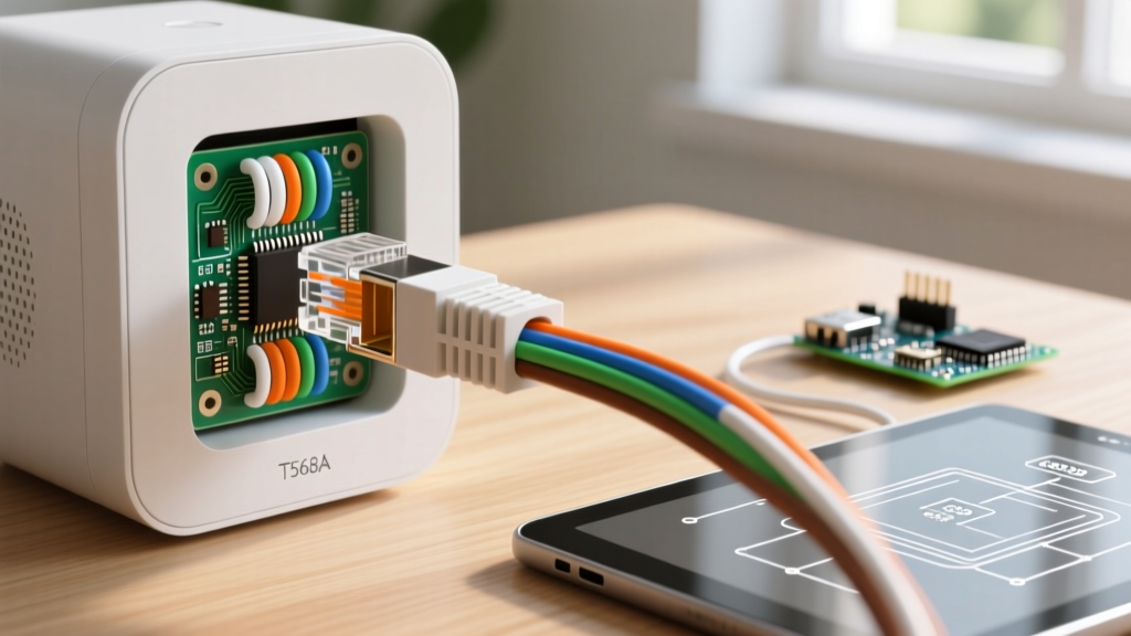
Before terminating a cable for a smart appliance hub, you must select the correct pinout standard. The Telecommunications Industry Association (TIA) recognizes two primary wiring schemes for 8P8C (commonly called RJ45) connectors: T568A and T568B. While both carry data identically, T568B has become the de facto standard for commercial and smart home appliance installations in North America.
Below is the definitive T568B pinout matrix. Notice how the pairs are allocated, which is especially critical when mapping Power over Ethernet (PoE) delivery to high-draw appliances.
| Pin | Wire Color (T568B) | Function (1000BASE-T) | PoE++ (802.3bt) Power Role |
|---|---|---|---|
| 1 | White/Orange | TX+ / Data | Positive Voltage (Pair 2) |
| 2 | Orange | TX- / Data | Positive Voltage (Pair 2) |
| 3 | White/Green | RX+ / Data | Negative Return (Pair 3) |
| 4 | Blue | BI_DD+ / Data | Positive Voltage (Pair 1) |
| 5 | White/Blue | BI_DD- / Data | Positive Voltage (Pair 1) |
| 6 | Green | RX- / Data | Negative Return (Pair 3) |
| 7 | White/Brown | BI_DC+ / Data | Negative Return (Pair 4) |
| 8 | Brown | BI_DC- / Data | Negative Return (Pair 4) |
Power over Ethernet (PoE) for High-Wattage Appliances
When wiring appliances like PTZ (Pan-Tilt-Zoom) outdoor cameras or smart home central servers, standard PoE (15.4W) is insufficient. The 2026 appliance ecosystem heavily utilizes the IEEE 802.3bt (PoE++) standard, which pushes up to 90W of power through all four twisted pairs simultaneously.
This massive power delivery introduces thermal challenges. If your wiring diagram for RJ45 is executed poorly, or if you use substandard cables, the resistance will generate heat, potentially melting the connector housing or triggering the appliance's internal thermal shutoff.
Cable Selection: Cat5e vs. Cat6 vs. Cat6a
- Cat5e (24 AWG): Maximum resistance. Not recommended for 802.3bt PoE++ appliance runs exceeding 100 feet due to severe voltage drop and bundle heating.
- Cat6 (23 AWG): The baseline for modern smart appliances. The thicker 23 AWG copper reduces resistance by roughly 20% compared to Cat5e, safely handling 60W (Type 3 PoE) over standard distances.
- Cat6a (23 AWG, Shielded): Mandatory for 90W (Type 4 PoE) appliances. The shielding prevents Alien Crosstalk (AXT) and provides superior thermal dissipation for high-wattage smart hubs.
Step-by-Step Appliance Wiring Tutorial: Terminating Cat6a
Terminating an RJ45 connector for a smart appliance requires precision. The most common failure mode in DIY appliance wiring is split pairs or excessive untwisting, which destroys the cable's impedance and causes Near-End Crosstalk (NEXT).
Required Tools & Materials
- Klein Tools VDV226-110 Pass-Thru Crimper (~$75): Essential for clean Cat6a terminations.
- Leviton 88086-R Cat6a Pass-Thru Connectors (~$1.20/ea): Features a built-in ground for shielded cables.
- Fluke Networks MicroScanner PoE (~$450): Verifies PoE class and wiremap before plugging in the appliance.
- 1000ft Spool of Pure Copper Cat6a (~$180): Never use CCA (Copper Clad Aluminum) for PoE appliances; CCA oxidizes and poses a fire hazard under high-wattage PoE.
The Termination Process
- Strip the Jacket: Remove exactly 2.5 inches of the outer PVC jacket using a precision stripping tool. Do not nick the internal copper conductors.
- Drain Wire Preparation: If using shielded Cat6a, fold the braided shield and drain wire back over the jacket. This must contact the metal shell of the RJ45 connector to ground the appliance properly.
- Align to T568B: Arrange the wires in the T568B sequence (White/Orange, Orange, White/Green, Blue, White/Blue, Green, White/Brown, Brown).
- The 0.5-Inch Rule: Trim the wires evenly. Critical: The distance from where the cable jacket ends to where the wires enter the connector pins must not exceed 0.5 inches. Untwisting the pairs beyond this limit ruins the high-frequency data integrity required by smart appliances.
- Insert and Crimp: Push the wires through the Pass-Thru connector until the copper ends protrude from the front. Seat the cable firmly into the crimping die and squeeze until the ratcheting mechanism releases.
- Trim and Test: Use the built-in blade on the crimper to shave the protruding copper ends flush. Test with a PoE verifier before connecting to the appliance.
Expert Insight: When wiring smart HVAC controllers that utilize RS-485 over Ethernet adapters, always verify that the appliance manufacturer does not require a proprietary pinout. Some industrial appliances use Pins 4, 5, 7, and 8 for serial data rather than standard PoE, which can fry a standard network switch if miswired.
Advanced Troubleshooting: Beyond the Basic Link Light
When an appliance fails to boot or randomly reboots, DIYers often blame the appliance's internal power supply. In reality, the issue usually lies in the RJ45 termination or the cable run. Here is how to diagnose advanced RJ45 appliance failures:
1. Appliance Reboots Under Load
The Symptom: A PoE security camera works fine during the day but reboots at night when the IR illuminators (infrared LEDs) turn on.
The Cause: Voltage drop. The IR array draws an extra 15W, pushing the cable past its power delivery threshold. If you used Cat5e or a run longer than 150 feet, the voltage at the appliance drops below the 42.5V minimum required by the IEEE standard.
The Fix: Upgrade the cable to Cat6a, or install a mid-span PoE++ injector (like the Ubiquiti UPOE-af) closer to the appliance to boost the voltage.
2. Intermittent Data Drops on Smart Hubs
The Symptom: A smart home hub drops offline for 3 seconds every few hours, disrupting connected smart locks and thermostats.
The Cause: Near-End Crosstalk (NEXT) caused by untwisting the wire pairs too far back inside the RJ45 boot, or running the Ethernet cable parallel to high-voltage AC appliance lines (like a 240V dryer circuit).
The Fix: Re-terminate the RJ45 connector, strictly adhering to the 0.5-inch untwist rule. Ensure a minimum 12-inch separation from AC mains wiring, as mandated by the National Electrical Code (NFPA 70).
3. Thermal Throttling in Wall Cavities
The Symptom: The RJ45 wall plate feels warm to the touch, and the connected smart display dims its screen unexpectedly.
The Cause: Bundle heating. When multiple Cat6 cables carrying 60W+ PoE are zip-tied tightly together inside an insulated wall cavity, the center cables cannot dissipate heat, raising the internal temperature past 60°C and increasing copper resistance.
The Fix: Remove tight zip-ties and use Velcro straps to allow airflow between cables. Limit high-wattage PoE bundles to a maximum of 24 cables per conduit.
Final Thoughts on Appliance-Grade RJ45 Wiring
Mastering the wiring diagram for RJ45 is no longer just an IT skill; it is a fundamental requirement for modern electrical and appliance installations. By respecting the T568B pinout, utilizing pure copper Cat6a cabling, and adhering to strict termination tolerances, you ensure that your smart appliances operate reliably for years to come. Always verify your work with a PoE-capable certifier before energizing high-value smart home equipment.