
Introduction to EZGO Electrical Architectures
When troubleshooting or upgrading your fleet, mastering the wiring diagram for EZGO electric golf cart models is the difference between a quick fix and a fried $600 motor controller. Unlike gas-powered counterparts, electric EZGOs rely on complex DC routing, logic signals, and high-amperage solenoids to manage torque and speed. Whether you are working on a legacy TXT or a modern RXV, the electrical topology dictates how power flows from the battery bank to the drive motor.
The Core Platforms: TXT vs. RXV
Before tracing a single wire, you must identify your drive system. EZGO primarily utilizes two distinct architectures in their electric lineup:
- EZGO TXT (Series & PDS/Shunt): Produced heavily from 1996 through 2013 (and available as a base model later). Uses DC motors. Series systems route full battery current through the Forward/Reverse (F&R) switch, while PDS (Precision Drive System) uses a Separately Excited (SepEx) motor and low-current logic switching.
- EZGO RXV (AC Drive): Introduced in 2008 and standard on 2026 models. Features a 48V AC induction motor, regenerative braking, and an onboard charger (OBC) integrated directly into the motor controller. Direction is controlled entirely by software logic, eliminating the heavy-duty mechanical F&R switch.
Decoding the Wiring Diagram for EZGO Electric Golf Cart (TXT PDS & Series)
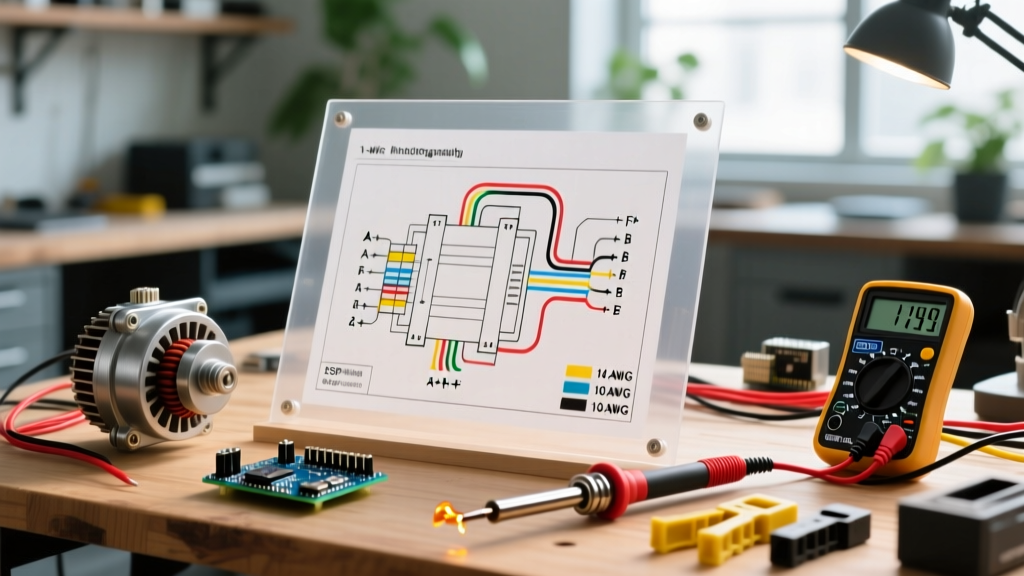
The TXT wiring diagram is divided into two distinct circuits: the high-current drive circuit and the low-current control circuit. In 48V PDS models, the main power cables are typically 2 AWG, while the control harness uses 16 AWG to 18 AWG wiring.
High-Current Drive Circuit Routing
- Battery Bank to Solenoid: Main positive (B+) travels from the battery pack positive terminal to the large post on the solenoid.
- Solenoid to Controller: The opposite large post on the solenoid connects directly to the B+ terminal on the Curtis 1205 or 1238 motor controller.
- Controller to Motor: The M+ and M- terminals on the controller route to the motor's A1, A2, S1, and S2 terminals. Crucial Note: Swapping S1 and S2 is how you reverse the motor's direction in a Series system, but in a PDS system, the F1 and F2 field windings are swapped via the controller's internal logic and external contactors.
Safety Warning: Always place the PDS "Tow/Run" switch in the "Tow" position before disconnecting any battery cables. Leaving it in "Run" can cause the controller to detect a rollback condition and engage the motor unexpectedly, leading to severe injury or arc flash.
Understanding the RXV 48V AC Wiring Architecture
The RXV wiring diagram represents a massive leap in EV technology. Because it uses an AC motor, the motor controller (often a Danaher or Curtis AC unit) acts as an inverter, converting 48V DC from the batteries into 3-phase AC power for the motor.
Key differences in the RXV diagram include:
- Elimination of the F&R Switch: The dashboard Forward/Reverse toggle is a simple 3-pin switch sending a 48V logic signal to the controller's J1/J2 harness pins.
- Integrated OBC: Unlike the TXT which uses a standalone Powerwise charger and separate OBC, the RXV's charging logic is embedded in the motor controller. The AC shore power connects to an onboard relay before reaching the battery bank.
- Brake Interlock: The RXV features an electromagnetic parking brake. The wiring diagram shows a dedicated 48V circuit that releases the brake only when the throttle is depressed and the key is ON.
Component Reference & Voltage Testing Matrix
Use this matrix when diagnosing issues with a digital multimeter. For accurate readings, reference the Fluke multimeter testing guidelines to ensure your CAT rating is appropriate for DC inductive loads.
| Component | Resting Voltage (48V System) | Under Load / Active | Common Failure Mode & Cost (2026) |
|---|---|---|---|
| Main Solenoid | 48V-52V (Large Posts) | 48V across both posts; 0V drop | Pitted copper contacts causing voltage drop. Replacement: $65-$90. |
| MCOR (Throttle Box) | 0.8V - 1.0V (Signal Wire) | Ramps smoothly to 3.2V - 3.6V | Worn potentiometer wiper causing erratic acceleration. Replacement: $130-$160. |
| Pre-Charge Resistor | N/A (Passive) | Carries initial surge to caps | Burnt out (open circuit) preventing solenoid engagement. Replacement: $12. |
| Motor Controller | 48V-52V (B+ to B-) | Outputs PWM / 3-Phase AC | Blown MOSFETs from pre-charge failure. Replacement: $450-$750. |
Common Wiring Failures & Diagnostic Edge Cases
The "Solenoid Click but No Movement" Paradox
A frequent issue when following a generic wiring diagram for EZGO electric golf cart repairs is ignoring the pre-charge circuit. When you press the throttle, you might hear the solenoid "click," but the cart won't move. While the solenoid's internal coil is engaging, the main high-amperage contacts may be failing to pass current. Alternatively, if the 250-ohm, 5-watt pre-charge resistor is missing or broken, the controller's internal capacitors draw a massive inrush current. Over time, this arc-welds the solenoid contacts or blows the controller's main fuse. Always verify continuity across the pre-charge resistor during annual maintenance.
MCOR Calibration and Throttle Dead-Zones
The Motor Controller Output Regulator (MCOR) replaced the older mechanical V-Glide. The MCOR uses a non-contact Hall-effect sensor or a precision potentiometer to send a 0-5V signal to the controller. If your wiring diagram shows a 4-wire MCOR (Power, Ground, Signal 1, Signal 2), the controller monitors both signals for redundancy. If Signal 1 reads 1.5V but Signal 2 does not read the exact inverse or proportional value, the Curtis motor controller will trigger an HPD (High Pedal Disable) fault, assuming the throttle is stuck. This prevents runaway carts but leaves owners stranded.
Integrating Lithium BMS into the EZGO Wiring Harness
As of 2026, lead-acid to lithium (LiFePO4) conversions are standard practice for EZGO fleet upgrades. When adapting the wiring diagram for an EZGO electric golf cart to accommodate a 48V lithium battery with an integrated Battery Management System (BMS), the charge and discharge pathways must be segregated. Unlike lead-acid banks that accept charge and discharge through the same main terminals, most high-capacity golf cart lithium batteries feature separate charge and discharge ports.
- Discharge Port (C- / P-): Connects to the cart's main negative cable leading to the motor controller's B- terminal. This port handles the 200A+ continuous draw and regenerative braking surges.
- Charge Port (C+ / P+): Connects exclusively to the onboard charger or external charging receptacle. The BMS uses this port to balance cells and manage thermal cutoffs during the charging cycle.
Failing to separate these circuits or bypassing the BMS charge port will result in the BMS tripping its internal MOSFET protection during regenerative braking, instantly cutting power to the cart while driving.
Upgrading and Modifying the Harness Safely
When adding accessories like LED light bars, voltage reducers, or digital dash displays, never tap directly into the controller's logic harness or the solenoid's activation circuit. The controller's internal DC-DC converter (if equipped) is typically rated for only 10 to 15 amps. Drawing accessory power from the key switch circuit will overload the 10A fuse and cause the entire cart to shut down.
Proper Accessory Wiring Protocol:
- Install a heavy-duty 12V voltage reducer (minimum 16A continuous, 30A peak) directly to the main battery pack's total positive and total negative terminals.
- Use a dedicated relay harness for high-draw accessories (e.g., 50W+ LED bars).
- Ensure all new wiring is routed away from the motor controller's high-frequency PWM cables to prevent electromagnetic interference (EMI), which can cause erratic throttle behavior.
When routing high-amperage DC cables and integrating new charge ports, always adhere to NFPA 70 (National Electrical Code) standards for DC overcurrent protection and wire ampacity to prevent thermal runaway. By understanding the specific logic flows and high-current pathways detailed in your cart's schematic, you can safely diagnose faults, perform accurate voltage-drop tests, and execute reliable upgrades.