
The Definitive Guide to 220V Air Compressor Wiring
Wiring a heavy-duty air compressor is one of the most demanding DIY electrical projects you can undertake. Whether you are installing a 5HP Quincy QT-5 in a professional auto shop or setting up a California Air Tools 10020C in your home garage, understanding the exact wiring diagram for 220 volt air compressor setups is non-negotiable. While colloquially referred to as "220V," modern North American electrical grids deliver a nominal 240V to these circuits. This guide provides a professional, step-by-step walkthrough grounded in the 2023/2026 National Electrical Code (NEC) standards, ensuring your motor gets the clean, stable power it needs to overcome massive Locked Rotor Amps (LRA) during startup.
Safety Warning: Working inside a live electrical panel carries a severe risk of arc flash and electrocution. Always verify the main breaker is OFF and use a non-contact voltage tester and a multimeter to confirm zero energy before touching any bus bars. If you are unsure about your panel's capacity, consult a licensed electrician.
Anatomy of a 240V Compressor Circuit
Unlike standard 120V household circuits that use one hot wire, one neutral, and one ground, a 240V compressor circuit relies on two out-of-phase hot legs (L1 and L2) and an Equipment Grounding Conductor (EGC). Because the motor windings are designed to operate across the 240V potential difference between the two hot legs, a neutral wire is not required for standard single-phase compressor motors. Adding a neutral to a dedicated 240V motor circuit is a waste of copper and violates NEC Article 210.4 regarding multiwire branch circuits.
Understanding Locked Rotor Amps (LRA) vs. Full Load Amps (FLA)
When an induction motor starts, it draws a massive inrush current—often 5 to 7 times its running current. This is the Locked Rotor Amps (LRA). Your wiring diagram and breaker sizing must account for this surge. If you size your breaker strictly to the Full Load Amps (FLA), the breaker will trip instantly every time the compressor kicks on. According to NFPA 70 (National Electrical Code) Article 430.52, the branch circuit short-circuit and ground-fault protection device (your breaker) is allowed to be sized significantly higher than the FLA to accommodate this startup surge, while the motor's internal thermal overload protects against sustained overcurrent.
Wire Gauge and Breaker Sizing Matrix
Choosing the correct wire gauge and breaker size is the most critical step in your wiring diagram planning. The table below outlines standard single-phase 240V compressor sizing based on NEC Table 430.248 and 430.52. Always verify the FLA on your specific motor's nameplate, as efficiency ratings vary by manufacturer.
| Motor HP | Approx. FLA (240V) | Min. Copper Wire Gauge (THHN) | Max Inverse-Time Breaker | Conduit Size (EMT) |
|---|---|---|---|---|
| 2 HP | 12.0 Amps | 12 AWG | 30A (2-Pole) | 1/2 inch |
| 3 HP | 17.0 Amps | 10 AWG | 40A (2-Pole) | 1/2 inch |
| 5 HP | 28.0 Amps | 8 AWG | 70A (2-Pole) | 3/4 inch |
| 7.5 HP | 40.0 Amps | 6 AWG | 100A (2-Pole) | 3/4 inch |
Note: If your wire run exceeds 75 feet, you must upsize the wire by one gauge to mitigate voltage drop. A voltage drop greater than 3% at the motor terminals will cause excessive heat buildup and premature failure of the start windings.
Tools and Materials Checklist
Do not rely on cheap, generic components for high-draw motor circuits. Invest in professional-grade materials to ensure secure terminations and long-term reliability.
- Breaker: Eaton BR240 or Siemens Q240 (Ensure it matches your panel brand; never mix breaker brands in a residential load center).
- Wire: THHN/THWN-2 stranded copper (Black, Red, and Green).
- Conduit: 3/4" EMT (Electrical Metallic Tubing) with compression fittings.
- Pressure Switch: Square D 9013FHG12 (Adjustable 100-135 PSI, standard for most 5HP shop compressors).
- Tools: Klein Tools 11063 wire strippers, torque screwdriver, 3/4" Greenlee conduit bender, non-contact voltage tester, and digital multimeter.
Step-by-Step Wiring Walkthrough
Step 1: Panel Preparation and Breaker Seating
- Shut off the main breaker to de-energize the panel bus bars.
- Knock out a 3/4" hole on the side or bottom of the panel using a screwdriver and hammer, then attach your EMT conduit connector.
- Snap the 2-pole breaker into the panel. Ensure it spans across both opposing bus bars. This is what creates the 240V potential. If it seats on a single bus bar (which is physically prevented in modern panels but possible in older, damaged ones), you will only get 120V.
- Do not terminate the wires to the breaker yet.
Step 2: Pulling the THHN Conductors
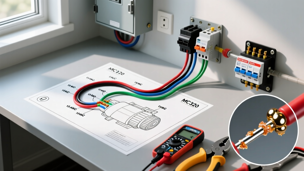
For a 5HP compressor, you will be pulling three 8 AWG THHN wires: Black (L1), Red (L2), and Green (Ground). Use a fiberglass fish tape and apply a light coat of wire-pulling lubricant if navigating more than two 90-degree bends. Leave at least 8 inches of slack at both the panel and the compressor pressure switch. Strip exactly 5/8" of insulation from the ends using your Klein strippers to ensure no bare copper is exposed outside the terminal lugs, which is a primary cause of arc faults.
Step 3: Wiring the Pressure Switch (The Critical Node)
The pressure switch acts as the brain of the compressor, making and breaking the 240V circuit based on tank PSI. The Square D 9013FHG series is the industry standard.
- Line Side (Power In): Connect the Black wire from the panel to the L1 terminal and the Red wire to the L2 terminal. Torque these screws to 12-15 in-lbs to prevent heat buildup from loose connections.
- Load Side (Motor Out): Connect a new set of Black and Red wires running to the motor to the T1 and T2 terminals.
- Grounding: Splice the Green ground wires together using a copper crimp sleeve or a wire nut, and attach a pigtail to the green grounding screw on the metal switch housing.
- Unloader Valve: If your switch features an unloader valve port (usually a 1/4" brass fitting on the bottom), ensure the copper tubing connects securely to the check valve on the tank. This bleeds head pressure so the motor can restart under zero load.
Step 4: Motor Junction Box Termination
Open the motor's peckerhead (junction box). For a dedicated 240V single-phase motor, you will typically see terminals labeled T1, T2, T3, and T4 (or simply 1, 2, 3, 4 for dual-voltage motors).
For a standard 240V setup on a dual-voltage motor: Connect T1 and T2 together, and T3 and T4 together. Bring your L1 (Black) to the T1/T2 junction, and L2 (Red) to the T3/T4 junction. Always refer to the specific wiring diagram printed on the inside of the motor's junction box cover, as manufacturer color codes (e.g., P1, P2, T2, T3) vary slightly between Baldor, Leeson, and WEG motors.
Integrating Start and Run Capacitors
Most 220V compressors above 2HP utilize a centrifugal start switch and a start capacitor to generate the phase shift needed for high starting torque. The start capacitor (usually a black cylindrical housing, 200-300 µF) is wired in series with the centrifugal switch and the start winding.
Expert Troubleshooting Tip: If your compressor hums loudly but fails to spin, and the breaker eventually trips, do not immediately assume the motor is dead. In 80% of these cases, the start capacitor has failed, or the centrifugal switch contacts are pitted and failing to engage. Use a multimeter with a capacitance setting to test the capacitor; if it reads more than 10% below its rated µF, replace it with an identical Dayton or Genteq equivalent.
Addressing Thermal Overloads and Magnetic Starters
For compressors 5HP and larger, the NEC and OSHA electrical safety standards strongly recommend (and often require in commercial settings) the use of a magnetic motor starter with an integrated thermal overload relay. A simple pressure switch cannot safely break the high-inductance arc of a 5HP motor stopping under load.
In this configuration, the 240V power flows from the breaker to the pressure switch, then to the coil of the magnetic contactor. The heavy-gauge motor power flows directly through the contactor's main contacts and the thermal overload block. Set the thermal overload dial precisely to the motor's FLA nameplate rating. This provides the precise, localized protection that a massive 70A branch breaker cannot offer.
Final Commissioning and Testing
Before energizing the circuit, double-check every termination. Tug gently on each wire to ensure it is securely seated in the lug.
- Turn on the main panel breaker.
- Measure the voltage at the Line side of the pressure switch with your multimeter. You should read between 236V and 244V.
- Flip the pressure switch to the "Auto" or "On" position.
- Listen for the motor to spool up. It should reach full RPM within 1.5 seconds. If it lingers in a low hum, immediately cut power and check your capacitor and start winding connections.
- Allow the compressor to build to its cut-out pressure (e.g., 135 PSI). Verify that the pressure switch clicks off and the unloader valve aggressively vents the head pressure.
By adhering strictly to this wiring diagram and respecting the physics of high-draw inductive loads, your 220V air compressor will deliver decades of reliable service. For more insights on optimizing your shop's pneumatic efficiency, refer to the U.S. Department of Energy's guide on Compressed Air Systems, which details how proper electrical supply and leak mitigation can reduce your compressor's energy consumption by up to 30%.