
The Divide: Chassis vs. House Wiring in Motorhomes
When converting a school bus, expedition truck, or Class A motorhome, beginners often conflate the vehicle's electrical system with the living quarters. In the RV industry, these are strictly separated into the chassis (engine, alternator, headlights, starter) and the house (living space appliances, lighting, HVAC). When DIYers search for a standard residential wiring diagram for house applications, they often make the fatal mistake of applying those same NEC (National Electrical Code) rules to a rolling, vibrating vehicle. An RV or Skoolie requires adherence to NFPA 1192 (Standard on Recreational Vehicles) and RVIA guidelines, which account for vibration, thermal extremes, and mobile grounding topologies.
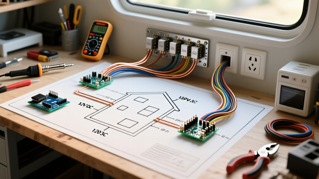
As of 2026, while 48V DC architectures are gaining traction in heavy expedition vehicles to reduce amperage, the 12V DC and 120V AC split-phase system remains the undisputed king of the Skoolie and Class B van conversion due to universal parts availability and appliance compatibility. This guide breaks down the exact architecture of a modern, high-capacity RV house wiring diagram.
CRITICAL SAFETY WARNING: Never bond the DC negative ground to the AC safety ground in an RV house system unless specifically dictated by the inverter/charger's internal relay logic during shore-power pass-through. Improper neutral-ground bonding is the leading cause of lethal stray voltage in metal-bodied vehicles like school buses.
Core Components of an RV Wiring Diagram for House Systems
A robust house system must handle high surge loads (like an air compressor or microwave startup) while maintaining clean sine-wave power for sensitive electronics. Below is the component matrix for a premium 2026 Skoolie build, utilizing top-tier marine-grade hardware.
| System Component | Recommended Model (2026) | Wire Gauge / Protection | Est. Cost (USD) |
|---|---|---|---|
| Inverter/Charger | Victron MultiPlus-II 12/3000/120-50 | 2/0 AWG / 400A Class T Fuse | $1,450 |
| Battery Bank | 4x Battle Born BB10012 (100Ah LiFePO4) | 2/0 AWG to 400A Busbars | $3,100 |
| Solar Charge Controller | Victron SmartSolar MPPT 150/60 | 6 AWG / 80A MIDI Fuse | $420 |
| DC Distribution | Blue Sea Systems ST Blade 12-Circuit | 4 AWG Feed / 100A Breaker | $45 |
| AC Distribution Panel | Progress Dynamics PD4560K1P4SS | 10 AWG Branches / 30A Main | $210 |
For comprehensive schematics on integrating these specific Victron components, the Victron Energy Wiring Diagrams portal provides interactive, load-tested topologies that account for the MultiPlus-II's internal transfer switch and PowerAssist logic.
Step-by-Step: Routing the 12V DC House Branches
The 12V DC side of your wiring diagram for house systems is unforgiving regarding voltage drop. Unlike 120V AC, a 12V system pushes high amperage, meaning undersized wires will result in dim lights, tripped low-voltage disconnects (LVD), and potential fire hazards.
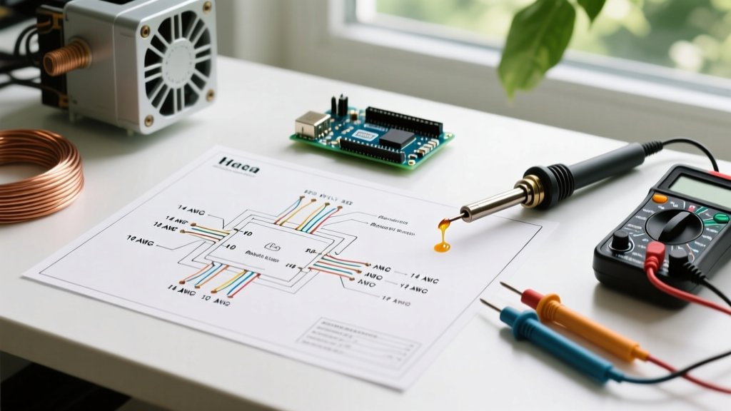
- Calculate Voltage Drop First: Use a 3% maximum voltage drop threshold for critical loads (fridge, water pump) and 10% for non-critical LED lighting. For a 40-foot school bus, running 12 AWG wire to the rear for a 10A water pump will result in a 0.8V drop. Upgrade to 10 AWG or even 8 AWG for long longitudinal runs.
- Use Stranded Marine Wire Only: Never use solid-core THHN residential wire in a vehicle. The constant vibration of a diesel chassis will cause solid copper to work-harden, snap, and arc inside walls. Use tinned, stranded marine wire (like Ancor Marine) to resist corrosion and vibration fatigue.
- Centralize the DC Distribution: Mount your Blue Sea ST Blade fuse block within 18 inches of the main battery busbars. Feed the block using 4 AWG wire protected by a 100A Blue Sea surface-mount circuit breaker.
- Implement Local Switching: For high-draw 12V appliances like a Webasto or Rixen hydronic heater, do not route the high-current path through a dashboard toggle switch. Use a standard automotive relay (Bosch style, 40A) triggered by a low-current 18 AWG switch wire.
120V AC Integration: Inverter Topologies and Shore Power
The 120V AC side of the RV house wiring diagram bridges the gap between off-grid autonomy and campground hookups. The heart of this system is the Inverter/Charger with an internal Automatic Transfer Switch (ATS).
Handling the Transfer Switch and GFCI Protection
When you plug into a 30A or 50A shore power pedestal, the Victron MultiPlus-II detects the AC input, bypasses the inverter circuit, and passes shore power directly to the AC sub-panel while simultaneously using excess current to charge the LiFePO4 bank.
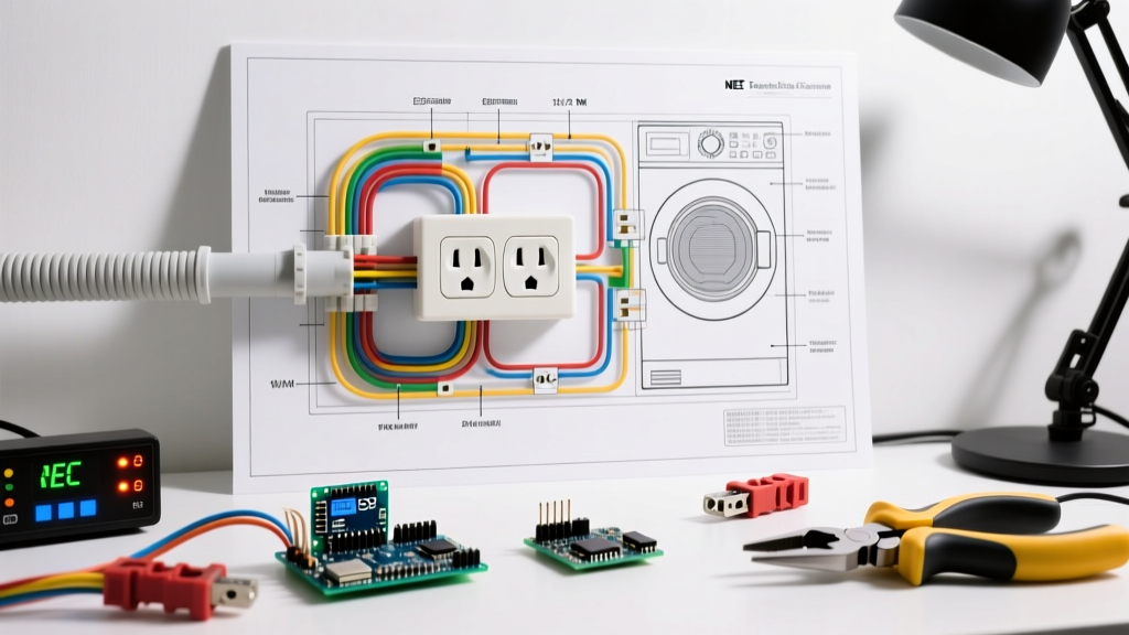
According to the Recreation Vehicle Industry Association (RVIA) standards and NFPA 1192, GFCI (Ground Fault Circuit Interrupter) protection is mandatory for any 120V AC receptacle located within 6 feet of a water source. In a Skoolie or RV wiring diagram, this means:
- Kitchen Countertops: Must be on a dedicated 20A GFCI breaker or protected by the first GFCI receptacle in the daisy chain.
- Bathroom/Wet Bath: Requires a dedicated GFCI protected circuit.
- Exterior Outlets: Must be GFCI protected and utilize weatherproof in-use covers.
Common Failure Modes in RV House Wiring
Even with a perfect schematic, physical installation errors cause 90% of RV electrical failures. Watch out for these specific edge cases:
- Undersized Busbars: A 3000W inverter pulling from a 12V battery bank at low voltage (11.5V) will draw over 260A continuously, with surges hitting 350A. Using standard 150A brass busbars will melt the insulation and cause a catastrophic fire. Always use minimum 400A rated, tin-plated copper busbars for the main battery-to-inverter runs.
- Chafing on Metal Bulkheads: School buses are essentially metal Faraday cages with sharp, stamped steel ribs. Passing wires through these ribs without heavy-duty rubber grommets or split loom tubing guarantees a short circuit within the first 5,000 miles of travel.
- The 'Floating Neutral' Hazard: In residential homes, the neutral and ground are bonded at the main panel. In an RV, if you bond neutral and ground at your AC sub-panel, and then plug into shore power (which also has a bonded neutral at the pedestal), you create a parallel neutral path. This energizes the chassis of the bus. The neutral-ground bond must only occur at the source (inside the inverter when off-grid, or at the shore power inlet when plugged in).
For deeper insights on selecting the correct overcurrent protection to prevent these failures, refer to the Blue Sea Systems Circuit Breaker Selection guide, which details the difference between thermal and magnetic trip curves in high-vibration environments.
FAQ: RV House Electrical Questions
Can I use standard residential Romex (NM-B) wire for the 120V AC house wiring?
Technically, NM-B is permitted by some loose interpretations of mobile codes, but it is highly discouraged and often fails RVIA inspection. The paper wrapping inside Romex wicks moisture, and the solid copper conductors snap under road vibration. Always use stranded, THHN/THWN wire pulled through flexible split loom or PVC conduit for 120V AC branches in a vehicle.
How do I wire a 12V DC air conditioner into the house diagram?
Modern 12V DC RV air conditioners (like the Dometic RTX or Nomadic X-Hal) draw massive startup current, often peaking at 80A to 100A for a few seconds. Your wiring diagram must include a dedicated 120A fuse and 2 AWG wire run directly from the main busbars to the AC unit, completely bypassing the standard DC fuse block to prevent voltage drop and nuisance tripping.
What is the purpose of the battery monitor shunt?
A shunt (like the Victron SmartShunt 500A) is a millivolt resistor placed on the negative main battery cable. It measures every single electron entering and leaving the battery bank, providing real-time state-of-charge (SOC) data via Bluetooth. Crucially, all negative loads and chargers must be wired to the load side of the shunt, not directly to the battery negative post, or the monitor will fail to track those specific circuits.