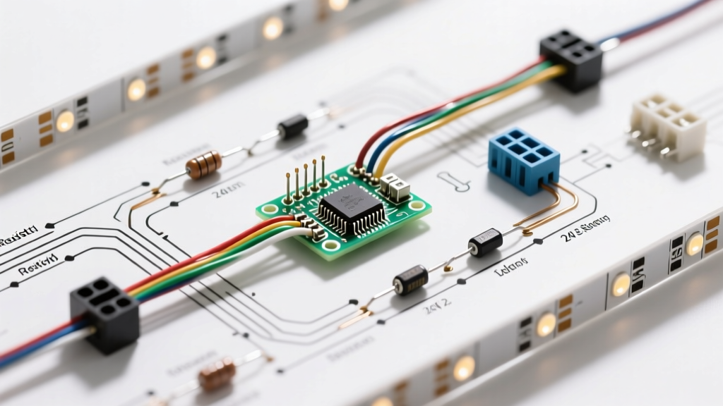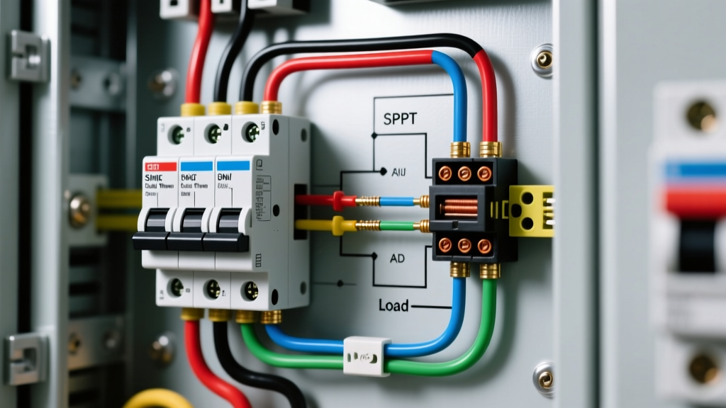

Mastering Panel Integration: The Wiring Diagram for Relay Switch Circuits
When integrating control circuits into a main distribution board or industrial control panel, understanding the wiring diagram for relay switch configurations is critical. Unlike simple automotive or breadboard setups, panel-mounted relays must interface seamlessly with miniature circuit breakers (MCBs), DIN-rail terminal blocks, and strict overcurrent protection standards. In 2026, as industrial IoT and smart building automation demand higher reliability, the margin for error in relay panel wiring has effectively dropped to zero.
This guide dissects the anatomy of panel-mounted relays, decodes standard IEC and NEMA schematic symbols, and provides actionable breaker sizing matrices to prevent contact welding, coil burnout, and catastrophic arc faults.
Anatomy of a DIN-Rail Panel Relay
Before tracing any wiring diagram for relay switch layouts, you must understand the physical and electrical architecture of modern DIN-rail relays. The industry standard for panel integration relies on modular electromechanical relays (EMRs) and solid-state relays (SSRs).
Electromechanical Relays (EMR)
Take the Finder 38 Series or Phoenix Contact RIF-1 (typically priced between $14 and $28 per unit). These consist of a base with screw or spring-cage clamps and a plug-in relay module. The standard Single Pole Double Throw (SPDT) configuration features three distinct circuit paths:
- Coil Pins (A1 / A2): The electromagnetic actuator. Common panel voltages are 24VDC, 120VAC, and 230VAC.
- Common Pin (11 or C): The input for the load circuit.
- Normally Open (14 or NO) & Normally Closed (12 or NC): The output paths to the load.
Solid-State Relays (SSR)
For high-cycle applications (e.g., PWM heating control), SSRs like the Schneider Electric Zelio RSL series are preferred. They lack moving parts and utilize optical isolation. However, their wiring diagrams mandate strict attention to thermal management; a 10A SSR generating 1.5W of heat requires a dedicated aluminum heatsink to maintain junction temperatures below 85°C.
Expert Insight: Never use a standard EMR for high-frequency switching. The mechanical bounce and arcing will destroy silver-alloy contacts within weeks. Always specify zero-cross SSRs for capacitive loads and random-fire SSRs for inductive loads.
Decoding the Wiring Diagram for Relay Switch Pinouts
Electrical schematics in panel design follow IEC 60617 or NEMA standards. Misinterpreting these diagrams is the leading cause of short circuits during commissioning.
IEC vs. NEMA Designations
| Function | IEC Standard Pin Designation | NEMA Standard Pin Designation |
|---|---|---|
| Coil Power | A1 (+/L1), A2 (-/N) | X1, X2 or Coil |
| SPDT Common | 11 | C (Common) |
| SPDT Normally Closed | 12 | NC |
| SPDT Normally Open | 14 | NO |
| DPDT Common (2nd pole) | 21 | C2 |
When reading a wiring diagram for relay switch logic, the coil circuit (A1/A2) is always drawn on the left or top of the schematic (the control side), while the contact circuit (11/12/14) is drawn on the right or bottom (the load side). This physical separation in the diagram reflects the galvanic isolation inherent in the relay.
Breaker Sizing and Wire Gauge Matrix
A relay is only as safe as the overcurrent protection device (OCPD) guarding it. Sizing the breaker for the coil circuit and the load circuit requires different calculations. The coil draws minimal current (typically 20mA to 40mA), while the load can draw up to the relay's maximum contact rating (usually 6A, 10A, or 16A).
Referencing NFPA 70 (National Electrical Code) Article 240 for overcurrent protection, here is the definitive matrix for panel integration:
| Circuit Type | Max Load / Draw | Recommended Breaker (MCB) | Wire Gauge (Copper, 75°C) | Protection Notes |
|---|---|---|---|---|
| 24VDC Coil Circuit | ~30mA | 2A Fast-Acting Fuse (No MCB) | 18 AWG (or 1.0mm²) | Use glass/ceramic fuses on the positive rail. |
| 120VAC Coil Circuit | ~40mA | 6A or 10A MCB (Curve C) | 14 AWG (or 2.5mm²) | Shared control circuit breaker for multiple coils. |
| Resistive Load (NO) | 10A (Steady State) | 10A MCB (Curve C) | 14 AWG (or 2.5mm²) | Breaker must not exceed relay contact rating. |
| Inductive/Motor Load | 6A (FLA) | 10A MCB (Curve D) + Overload | 12 AWG (or 4.0mm²) | Relay must be derated by 50% for inductive loads. |
Step-by-Step Panel Integration Workflow
Follow this precise sequence to wire a 120VAC coil, 10A SPDT relay into a standard distribution panel.
- Mount the Hardware: Snap the 35mm DIN rail into the enclosure. Mount the relay base, followed by the control MCB (e.g., Schneider iC60N 10A) and the load MCB.
- Wire the Control Side (A1/A2): Run 14 AWG wire from the control MCB's load terminal to a terminal block, then to A1. Wire A2 directly to the neutral busbar. Pro-Tip: Always place a flyback diode (for DC) or an RC snubber module (for AC) across A1 and A2 to suppress inductive voltage spikes that can fry upstream PLCs.
- Wire the Load Side (11/14): Run 14 AWG wire from the load MCB to the Common pin (11). Wire the Normally Open pin (14) to your target device (e.g., a solenoid valve or lighting contactor).
- Install the Module and Retainer: Plug the relay into the base. Install the plastic retainer clip (often overlooked, but critical to prevent vibration-induced disconnects in industrial panels).
- Commissioning Test: Energize the control breaker. Use a multimeter to verify 120VAC at A1/A2. Manually actuate the relay using the built-in test lever to verify continuity between 11 and 14 before applying full load power.
Common Failure Modes and Edge Cases
Even with a perfect wiring diagram for relay switch execution, real-world physics can cause catastrophic failures. Understanding these edge cases separates novice wiremen from senior panel builders.
1. Contact Welding from Capacitive Inrush
The Scenario: You wire a 10A relay to switch a bank of commercial LED high-bay lights. The steady-state draw is only 4A. However, LED drivers contain massive internal capacitors. Upon closure, the inrush current can spike to 200A for 2 milliseconds.
The Failure: The standard silver-nickel contacts melt and weld together. The relay fails in the 'ON' position, and the MCB does not trip because the steady-state current never exceeds 10A.
The Solution: Specify relays with Tungsten pre-contacts (like the Omron G7SA series) or use an SSR rated for high inrush. Alternatively, wire a Negative Temperature Coefficient (NTC) thermistor in series with the load to limit inrush current.
2. AC Coil Chatter and Burnout
The Scenario: The voltage at A1/A2 drops below 85% of the nominal rating due to voltage sag on a long control wire run.
The Failure: The AC relay's shading ring fails to maintain the magnetic field during the zero-crossing of the AC sine wave. The armature chatters violently at 120Hz. This generates massive heat, melting the coil bobbin and causing an internal short.
The Solution: Keep control wire runs under 50 feet for 24VDC, or step up to 120VAC for longer runs. Always measure voltage at the relay terminals under load, not just at the breaker.
Advanced Configurations: Latching and Safety Relays
For critical infrastructure, standard SPDT relays are insufficient. Modern panel designs increasingly utilize specialized relay architectures.
Safety Relays (Force-Guided Contacts)
When wiring emergency stop (E-Stop) circuits or light curtains, you must use force-guided safety relays (e.g., Phoenix Contact PSR series). In these wiring diagrams, the Normally Open and Normally Closed contacts are mechanically locked together. If a NO contact welds shut due to a fault, the NC contact is physically prevented from closing, allowing the safety controller to detect the failure and halt the machine. Standard relays cannot provide this diagnostic feedback.
Latching Relays for Power Outage Resilience
In HVAC and lighting panels, magnetic latching relays (bistable relays) are used to maintain state during a power loss. They require a momentary pulse to A1 to set, and a pulse to a separate pin (often A3) to reset. This eliminates continuous coil heat generation and ensures the panel resumes exactly as it was after a grid failure.
Summary Checklist for Panel Builders
- Verify coil voltage matches the control circuit MCB output exactly.
- Derate contact ratings by 50% for motors and 75% for highly capacitive loads.
- Always use ferrules on stranded wire entering relay screw terminals to prevent stray strands from causing phase-to-ground faults.
- Install RC snubbers across AC coils and flyback diodes across DC coils to protect upstream solid-state logic.
- Label all wires at both ends using thermal-transfer wire markers, matching the wire numbers on the schematic.
By treating the wiring diagram for relay switch layouts not just as a map, but as a blueprint for thermal, magnetic, and mechanical management, you ensure your breaker panels operate safely and reliably for decades.