
Understanding the Modern Fisher Multiplex Architecture
Snow plow electrical systems endure some of the most extreme environmental conditions of any automotive accessory. Between sub-zero temperatures, high-pressure road salt, and severe mechanical vibration, a marginal wiring setup will fail rapidly. When consulting a wiring diagram for Fisher plow setups, technicians and DIYers must recognize that modern Fisher Engineering systems (such as the Minute Mount 2, EZV, and XtremeV) have largely abandoned the old 4-plug relay-based architectures in favor of a highly efficient 3-plug multiplex system.
This multiplex architecture reduces the physical number of wires crossing the firewall, minimizes voltage drop, and centralizes diagnostic capabilities within the truck-side Isolation Module. Whether you are retrofitting an older truck or diagnosing a dead hydraulic pump, mastering the wiring diagram for Fisher plow 3-plug configurations is essential for reliable winter operations.
Core Components & Wire Gauge Specifications
Before tracing individual circuits, you must understand the physical hardware and the strict wire gauge requirements dictated by SAE International Wiring Standards for high-draw automotive applications. The hydraulic motor on a Fisher plow can draw upwards of 120 to 150 amps under heavy load (such as when lifting a fully loaded V-plow). Using undersized wire will result in severe voltage drop, melted insulation, and solenoid failure.
| Component | Function | Required Wire Gauge | Estimated 2026 Replacement Cost |
|---|---|---|---|
| Motor Power Harness | Delivers high-amperage DC power from the battery to the hydraulic pump solenoid. | 2 AWG or 4 AWG (Welding Cable) | $85 - $130 |
| Heavy-Duty Solenoid | Acts as the high-current switch to engage the hydraulic motor (typically Trombetta style). | 10 AWG (Lugs) / 14 AWG (Trigger) | $65 - $95 |
| 11-Pin Control Harness | Carries multiplexed signals for lighting and valve coil actuation. | 18 AWG to 20 AWG (Shielded) | $120 - $180 |
| Isolation Module | Decodes multiplex signals, protects truck lighting circuits, and provides diagnostic LED blinks. | N/A (Connects via OEM plugs) | $280 - $360 |
| Main Circuit Protection | Protects the main power feed from catastrophic short circuits. | 150A MAXI Fuse or Mega Fuse | $15 - $25 |
Step-by-Step: Reading the Wiring Diagram for Fisher Plow Harnesses
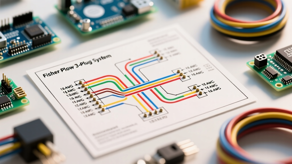
The modern Fisher 3-plug system is divided into three distinct physical connections at the front of the truck. Understanding how the wiring diagram maps to these physical plugs is the key to efficient troubleshooting.
1. The Power Circuit (Plug 1: 2-Pin Heavy Duty)
The first plug is strictly for high-current power. It consists of two massive pins housed in a weather-sealed rubber boot. According to the official Fisher Engineering Support documentation, this circuit bypasses the truck's ignition switch and connects directly to the battery's positive terminal via a 150A MAXI fuse.
- Pin 1 (Red Cable): Constant 12V+ from the battery. This feeds the large terminal on the truck-side solenoid.
- Pin 2 (Black Cable): Heavy-duty ground. This must be bonded directly to the truck's engine block or chassis ground stud, never to a painted surface or thin sheet metal.
2. The 11-Pin Control & Lighting Multiplex (Plug 2)
The second plug is the brain of the operation. It uses an 11-pin connector to transmit both lighting data and hydraulic valve commands. The wiring diagram for Fisher plow multiplex systems uses a pulse-width modulated (PWM) or serial data stream to communicate between the in-cab joystick controller and the Isolation Module.
- Pin A (Black): Module Ground.
- Pin B (Red): Switched 12V+ (Ignition source to wake the Isolation Module).
- Pin C (White/Blue): Multiplex Data Line 1 (Joystick to Module communication).
- Pin D (White/Green): Multiplex Data Line 2.
- Pins E through K: Dedicated circuits for plow headlights (high/low beam), turn signals, and marker lights. The Isolation Module intercepts the truck's OEM headlight signals and routes them to the plow when the system is powered on.
3. The Lighting Extension (Plug 3)
Depending on the exact model year and whether you are running an EZV or a straight blade (HTS), the third plug is often a dedicated lighting harness that Y-splits to the left and right plow headlamps. This separation ensures that if the heavy power plug is damaged during hitching, the lighting and control circuits remain intact and serviceable.
Pro-Tip from the Bench: Never use standard automotive bulb grease on the 11-pin multiplex connectors. The multiplex data lines operate on low-voltage, high-frequency signals. Standard grease can attract metallic dust and cause capacitance issues, leading to joystick communication errors. Always use a dedicated dielectric tune-up grease specifically rated for multi-pin data connectors.
Advanced Diagnostics & Troubleshooting Failure Modes
When a Fisher plow fails to operate, DIYers often immediately assume the hydraulic pump or motor is dead. However, ASE-certified electrical diagnostics dictate that we verify the circuit integrity first. Here is how to use a digital multimeter (DMM) to diagnose the most common failure modes found in the wiring diagram.
- The "Click-Click" Solenoid Chatter: If you press the raise button on the joystick and hear the solenoid rapidly clicking without the motor turning, you have a severe voltage drop. The control circuit is triggering the solenoid, but the high-current side cannot sustain the magnetic field. Fix: Perform a voltage drop test across the 150A MAXI fuse and the battery lugs. A drop of more than 0.2V under load indicates corroded lugs or a failing battery.
- Isolation Module LED Codes: The truck-side Isolation Module features a small diagnostic LED. If the plow lights do not switch over from the truck to the plow, check this LED. A solid light indicates normal operation. A flashing code (e.g., 3 flashes, pause, 3 flashes) indicates a specific short or open circuit in the lighting harness. Cross-reference the blink code with the Fisher service manual.
- Joystick Dead / No Power Light: If the in-cab controller does not light up, the issue is almost always Pin B (Switched 12V) on the 11-pin plug, or a blown 10A mini-fuse located in the truck's under-hood fuse box that feeds the ignition trigger wire.
- Corroded Control Pins: The 11-pin plug is highly susceptible to galvanic corrosion if the rubber dust cap is lost. If pins turn green (copper oxide) or white (aluminum oxide), the multiplex data signal will degrade. Clean with a specialized electrical contact cleaner and a fiberglass scratch pen—never a steel wire brush, which will strip the gold plating.
Installation Best Practices for Longevity
Proper routing is just as critical as the wiring diagram itself. When running the 2 AWG power cables through the firewall or along the frame rail, maintain a minimum clearance of 12 inches from hot exhaust components. Use split-loom tubing wrapped in high-temperature electrical tape to protect against abrasion. Furthermore, all ground connections must be sanded down to bare, shiny metal, treated with a light coat of anti-oxidant paste, and torqued to the manufacturer's specification (typically 15-20 ft-lbs for 3/8" ground studs).
Frequently Asked Questions
Can I convert my older 4-plug Fisher relay system to the 3-plug multiplex?
Yes, but it requires a comprehensive retrofit kit. You must replace the truck-side wiring harness, the Isolation Module, the in-cab joystick controller, and the plow-side control harness. While the initial cost is higher (roughly $600 to $800 in parts for 2026), the multiplex system drastically reduces future troubleshooting time and eliminates the need to replace multiple mechanical relays.
Why does my truck's headlight dim when I raise the plow?
This is a classic symptom of inadequate grounding or an undersized main power feed. The hydraulic motor is drawing 140+ amps, and if the plow's ground path is poor, it will attempt to ground through the truck's lighting harness, pulling voltage away from the headlights. Upgrading the ground cable to 2 AWG and ensuring a clean chassis bond will resolve this.
What happens if the 150A MAXI fuse keeps blowing?
A repeatedly blowing main fuse indicates a dead short to ground on the load side of the solenoid, or a seized hydraulic motor drawing locked-rotor amperage. Disconnect the motor, test the motor's internal resistance (which should be extremely low, typically less than 0.5 ohms), and inspect the power cable for pinch points where it may be rubbing against the truck's frame or the plow's A-frame.