
The Critical Role of Proper Fan Circuitry in Vehicles
Upgrading from a mechanical clutch fan to a high-CFM electric cooling fan—such as the popular Spal VA18BP10/C-39 or Flex-a-lite 295 dual fan kit—is one of the most effective ways to reclaim horsepower and improve low-speed cooling in classic cars, hot rods, and off-road vehicles. However, the most common point of failure in these conversions is not the fan motor itself, but an inadequate wiring harness. As of 2026, with modern brushless PWM (Pulse Width Modulation) fans drawing massive startup currents, relying on a direct-to-switch wiring method is a recipe for melted dash switches, voltage drops, and engine overheating.
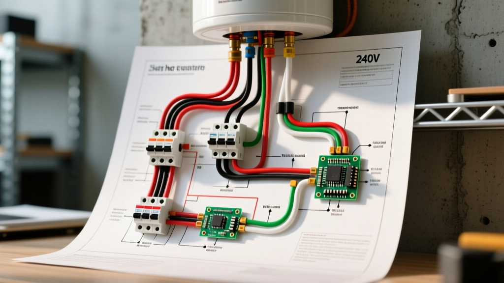
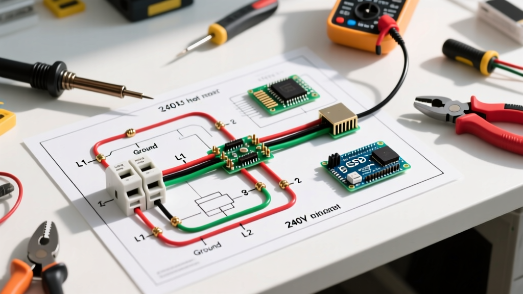
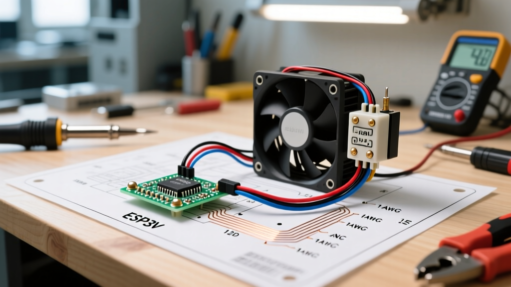
Understanding a proper wiring diagram for fan relays is mandatory. By utilizing a standard ISO mini 4-pin Bosch-style relay, you isolate the high-amperage fan circuit from the low-amperage control circuit, ensuring your thermal switch or ECU trigger is protected while delivering maximum voltage to the fan motor.
⚠️ SAE Safety & Wire Standard Notice: Never use cheap Copper-Clad Aluminum (CCA) wire sourced from unverified online marketplaces for under-hood automotive applications. CCA wire has a higher resistance and lower melting point than pure copper. Always specify TXL, GXL, or SXL cross-linked polyethylene insulated wire, which meets SAE J1128 standards and withstands under-hood temperatures up to 125°C (257°F).Core Components: Relays, Fuses, and Wire Gauges
Before tracing the wiring diagram, you must select the correct components. A standard 30A relay is often insufficient for high-performance dual fans that can pull 25A–35A continuously. For dual fan setups, use a 40A or 50A heavy-duty relay, or split the circuit into two separate 30A relays.
Wire Gauge Selection Based on SAE J1128
Automotive wire is rated differently than household NEC wire due to the 12V-14V DC environment and high ambient engine bay temperatures. Voltage drop is the enemy of electric motors; a fan receiving 10.5V instead of 13.8V will spin significantly slower, draw more amperage to compensate, and overheat.
| Wire Gauge (AWG) | Max Ampacity (SAE) | Best Application in Fan Circuit | Voltage Drop per 10ft (at 20A) |
|---|---|---|---|
| 16 AWG | 10 Amps | Relay Coil Control (Pins 86/85) | Not Recommended for Power |
| 14 AWG | 15 Amps | Single Small Fan Power (Up to 12A) | 0.51 Volts |
| 12 AWG | 20 Amps | Standard Single Fan Power (Up to 20A) | 0.32 Volts |
| 10 AWG | 30 Amps | Dual Fan Power / High-CFM Single | 0.20 Volts |
| 8 AWG | 40 Amps | Main Feed from Alternator/Battery | 0.12 Volts |
Step-by-Step: The Standard 4-Pin Relay Wiring Diagram for Fan
The standard 4-pin ISO relay features four numbered terminals: 30, 87, 86, and 85. Here is the exact routing for a single high-CFM cooling fan controlled by a dash switch or a radiator-mounted thermal probe.
- Pin 30 (Power In): Run a 10 AWG or 12 AWG wire from the positive terminal of the battery (or a high-amperage distribution bus). Crucial: Install a 30A or 40A ATO/ATC blade fuse within 6 inches of the power source to protect the wire in case of a short.
- Pin 87 (Power Out to Load): Run a 10 AWG or 12 AWG wire from Pin 87 directly to the positive terminal of the cooling fan motor.
- Pin 86 (Coil Power): Run a 16 AWG wire from a switched 12V ignition source (or directly to the battery if you want the fan to be able to run after the engine is off). Connect the other end to Pin 86.
- Pin 85 (Coil Ground / Trigger): Run a 16 AWG wire from Pin 85 to your control device. This can be a manual toggle switch grounded to the chassis, or a thermal switch (like the Hayden 3653) threaded into the radiator or engine block.
- Fan Ground: Connect the fan's negative wire directly to the vehicle chassis or engine block using a dedicated ring terminal and a star washer to bite through paint. Never ground the fan to the aluminum radiator core.
Integrating a Thermal Switch vs. PWM Controller
In traditional setups, a mechanical thermal switch (set to close at 185°F and open at 165°F) handles the ground path for Pin 85. While reliable, mechanical switches suffer from hysteresis and contact wear over time.
For modern 2026 builds, enthusiasts are moving toward solid-state PWM controllers (such as the Derale 16795 or custom Arduino-based MOSFET drivers). A PWM controller varies the fan speed based on coolant temperature, eliminating the massive amperage spike of a fan starting at 100% speed. When using a PWM controller, the controller itself handles the heavy switching via internal MOSFETs, and the standard relay is often bypassed entirely, with the PWM module wired inline between the fused battery feed and the fan motor.
Expert Tip: The Flyback Diode
If your fan relay is being triggered by a sensitive engine control unit (ECU) or a modern solid-state sensor, you must install a flyback diode (e.g., 1N4001) across the relay coil pins (86 and 85). When the relay opens, the collapsing magnetic field generates a reverse voltage spike that can exceed 100V, instantly frying ECU driver transistors. Wire the diode in reverse bias (cathode stripe pointing toward Pin 86) to safely recirculate and clamp this spike. Read more on protecting automotive electronics via Mad Electrical's relay technical guide.
Common Failure Modes & Troubleshooting
Even with a perfect wiring diagram for fan setups, real-world vehicle environments introduce variables that cause failures. Use a digital multimeter (DMM) to diagnose these specific edge cases:
- Relay Chatter (Rapid Clicking): This occurs when the thermal switch is placed too close to the fan airflow, causing the coolant surface temperature to rapidly fluctuate, or when there is a severe voltage drop in the 16 AWG control wire. Fix: Move the thermal probe to the engine block thermostat housing or upgrade the control wire to 14 AWG.
- Fan Runs Slow / Overheating Wiring: Caused by using undersized CCA wire or poor grounding. If the fan is rated for 20A but you measure 25A with an inductive clamp meter, the motor is starving for voltage and working harder. Fix: Perform a voltage drop test across the ground wire. A reading above 0.1V under load indicates a bad chassis ground. Scrape the paint and use a brass or copper ring terminal.
- Melted Fuse Holder: Standard ATC fuse holders with tin-plated brass contacts can overheat at continuous 25A+ loads. Fix: Upgrade to a heavy-duty ANL or MIDI fuse holder with copper contacts and a high-temperature housing for any circuit running over 25A continuously.
- Galvanic Corrosion in Radiator: If the fan was improperly grounded to the radiator support or core, stray DC current travels through the coolant. This causes rapid electrolysis, destroying aluminum radiators and heater cores from the inside out. For more on cooling system electrical issues, refer to AA1Car's cooling fan diagnostics.
Frequently Asked Questions (FAQ)
Can I wire two cooling fans to a single 4-pin relay?
Yes, but only if the combined continuous amperage draw of both fans does not exceed 80% of the relay's rated capacity (e.g., 24A on a 30A relay). You must also upgrade the main power wire (Pin 30) to 8 AWG to handle the combined load without voltage drop. For dual high-performance fans pulling 40A+ combined, use two separate relays triggered by the same thermal switch to ensure longevity and redundancy.
Why does my fan turn on when I turn the key off?
If your relay's Pin 86 is wired to a constant 12V battery source instead of an ignition-switched source, the fan will remain powered as long as the thermal switch is closed (engine is hot). While this is sometimes intentional to prevent heat soak after shutdown, it will drain your battery if the thermal switch fails in the closed position. Always use an ignition-switched feed or a dedicated timer-delay relay module for post-run cooling.
Are solid-state relays (SSRs) better for automotive fans?
Automotive-grade solid-state relays (like those from Littelfuse) offer infinite lifespans since they have no moving contacts to pit or arc. However, SSRs generate internal heat proportional to the current draw and require mounting to a metal heat sink. For standard 20A cooling fans, a high-quality mechanical ISO relay remains the most cost-effective and easily replaceable solution on the trail or at a car show.