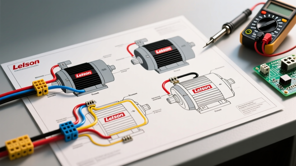

Introduction to Leeson Motor Terminal Configurations
Wiring an industrial or agricultural motor requires precision, and understanding Leeson electric motors wiring diagrams is critical for ensuring operational safety and longevity. Now fully integrated under the Regal Rexnord umbrella, Leeson remains a dominant force in the 2026 market for farm-duty, HVAC, and compressor motors. Whether you are installing a standard C143T 1.5 HP Farm Duty motor (retailing around $410 in 2026) or a heavy-duty C182T 3 HP compressor motor, the terminal block configurations follow strict NEMA MG 1 standards.
Unlike generic consumer-grade motors, Leeson industrial motors utilize standardized T-leads (T1 through T9) and P-leads (P1, P2) for thermal protection. Misinterpreting these diagrams is the leading cause of premature winding failure and voided warranties. This tutorial provides a deep-dive, electrician-level guide to wiring Leeson single-phase and three-phase motors, complete with voltage changeover matrices and NEC-compliant breaker sizing.
Single-Phase Leeson Motor Wiring (115V/230V Dual Voltage)
Most single-phase Leeson motors (such as the popular C56C jet pump and C143T farm duty series) are dual-voltage, capable of operating on either 115V or 230V. The terminal board typically features six main leads: T1, T2, T3, T4, T5, and T8.
- T1, T2, T3, T4: These represent the two main run windings.
- T5, T8: These represent the start winding, which is connected in series with the centrifugal switch and the start capacitor.
Voltage Changeover Matrix
To change the voltage, you must reconfigure how the run windings are connected (series for 230V, parallel for 115V) while ensuring the start winding always receives the correct line voltage. Below is the standard Leeson single-phase wiring matrix:
| Voltage | Line 1 (Hot) Connections | Line 2 (Neutral/Hot) Connections | Internal Ties (Wire Nuts/Jumpers) |
|---|---|---|---|
| 230V (High) | T1, T5 | T4, T8 | T2 to T3 |
| 115V (Low) | T1, T3, T5 | T2, T4, T8 | None (All connected to line) |
Expert Warning: Never apply 230V to a motor wired for 115V. The run windings will be in parallel, causing them to draw four times the normal current, instantly melting the winding insulation and tripping the main breaker.
Three-Phase Leeson Motor Wiring (Wye vs. Delta)
Three-phase Leeson motors, commonly used in industrial conveyor and heavy compressor applications, typically feature a 9-lead terminal board (T1 through T9). These motors can be wired in either Wye (Y) or Delta configurations, depending on the specific nameplate data. The most common configuration for modern Leeson 9-lead motors is the Wye (Y) connected dual-voltage setup (230V/460V).
9-Lead Wye (Y) Dual Voltage Configuration
In a Wye configuration, the internal windings meet at a common neutral point. Wiring requires specific pairing to balance the phase loads.
| Voltage | Phase A (L1) | Phase B (L2) | Phase C (L3) | Neutral Ties (Insulated) |
|---|---|---|---|---|
| 230V (Low) | T1 & T7 | T2 & T8 | T3 & T9 | T4, T5, T6 tied together |
| 460V (High) | T1 | T2 | T3 | T4-T7, T5-T8, T6-T9 |
For 460V operation, the windings are placed in series, effectively doubling the voltage rating while halving the current draw. Always use a calibrated multimeter to verify phase-to-phase voltage before energizing a newly wired 3-phase Leeson motor.
Thermal Overload Protection: Wiring P1 and P2 Terminals
A critical feature found on integral-horsepower Leeson motors is the internal thermal overload protector, identified by the P1 and P2 terminals. A common and catastrophic mistake made by novice technicians is wiring P1 and P2 in series with the main motor power line.
The P1/P2 circuit is a low-current pilot circuit, not a power circuit. These terminals contain a set of normally-closed (NC) contacts that open when the internal motor temperature exceeds safe limits (typically 130°C to 150°C for Class F insulation).
- Wire P1 and P2 in series with the contactor coil or the control circuit (e.g., a 24V or 120V PLC input).
- When the motor overheats, the P1-P2 circuit opens, de-energizing the contactor coil and dropping out the main power safely.
- Wiring P1/P2 directly into a 230V or 460V main power line will cause the internal thermal switch to arc and destroy itself upon the first motor startup.
Reversing Motor Rotation
Incorrect rotation on compressors or agricultural augers can cause severe mechanical damage. Reversing a Leeson motor requires swapping specific leads, but the method differs entirely between single-phase and three-phase models.
- Single-Phase: To reverse rotation, you must swap the start winding leads relative to the run winding. Swap T5 and T8. Do not swap the run winding leads (T1-T4), as this will not change the phase angle of the start circuit and the motor will continue to spin in the original direction.
- Three-Phase: Simply swap any two of the three main power leads (e.g., swap L1 and L2 at the contactor or terminal block). Swapping T1 and T2 is the standard industry practice.
Wire Gauge and Breaker Sizing (NEC 2026 Compliance)
Sizing conductors and overcurrent protection for Leeson motors must strictly adhere to NFPA 70 (National Electrical Code) Article 430. Motor circuits are unique because they must accommodate the Locked Rotor Amperage (LRA) during startup without nuisance tripping, while still protecting the wire from short circuits.
Below is a reference table for common Leeson single-phase motor sizes, based on NEC Table 430.248 for Full Load Amps (FLA) and standard inverse-time breaker sizing (typically 250% of FLA for single-phase).
| Motor HP | Voltage | FLA (Amps) | Min. Copper Wire (THHN) | Max Standard Breaker |
|---|---|---|---|---|
| 1.0 HP | 115V | 16A | 12 AWG | 30A |
| 1.0 HP | 230V | 8A | 14 AWG (12 AWG rec.) | 15A |
| 1.5 HP | 230V | 10A | 12 AWG | 20A |
| 2.0 HP | 230V | 12A | 12 AWG | 25A |
| 3.0 HP | 230V | 17A | 10 AWG | 35A |
Note: While NEC permits 14 AWG for certain low-amp motor circuits, best practice in 2026 industrial environments dictates a minimum of 12 AWG for mechanical durability and voltage drop mitigation over long agricultural runs.
Capacitor Testing and Replacement
Single-phase Leeson motors rely on capacitors to generate the phase shift required for starting torque. If your motor hums but fails to rotate, or trips the breaker instantly, the start capacitor is the primary suspect.
- Start Capacitors: Typically rated between 100µF and 300µF. They are only in the circuit for a fraction of a second until the centrifugal switch opens. If a start capacitor fails shorted, it will explode or vent electrolyte. Always replace with the exact microfarad (µF) rating and a voltage rating equal to or higher than the original (e.g., replacing a 125VAC cap with a 165VAC or 250VAC cap is safe and often extends lifespan).
- Run Capacitors: Found on Capacitor-Start/Capacitor-Run (CSCR) Leeson motors, these remain in the circuit continuously. They are usually rated between 10µF and 50µF at 370VAC or 440VAC. A failing run capacitor causes a drop in running torque and excessive heat in the start winding.
Always discharge capacitors using a 20,000-ohm, 5-watt bleeder resistor before handling. Shorting them with a screwdriver can weld the tool to the terminals and damage the capacitor's internal foil.
Troubleshooting Common Wiring Failures
Even with correct Leeson electric motors wiring diagrams, field conditions introduce variables. Here are three specific failure modes and their solutions:
- Motor Hums and Trips Breaker on 230V: The run windings are likely wired in parallel (115V configuration) while receiving 230V. Check the T2-T3 tie and ensure T1/T5 and T4/T8 are receiving line voltage.
- Motor Starts but Lacks Torque Under Load: The centrifugal switch may be stuck open, or the start capacitor is dead. The motor is running solely on the main run winding. Remove the rear bell end and inspect the switch contacts for pitting or mechanical binding.
- Contactor Chatters or Drops Out Randomly: If P1/P2 thermal overload wires are used, check for loose spade connections. The thermal switch is highly sensitive to voltage drops in the pilot circuit. Ensure pilot wires are at least 18 AWG and securely crimped.
Authoritative References and Standards
For further technical validation, always consult the manufacturer's specific nameplate data and current electrical codes. The wiring matrices provided above align with the NEMA MG 1 Motors and Generators standard, which dictates terminal markings and performance tolerances for all North American industrial motors. Additionally, ensure all installations comply with the latest Regal Rexnord Leeson technical bulletins and local AHJ (Authority Having Jurisdiction) interpretations of NEC Article 430.