
Introduction to Compressor Circuit Planning
Replacing a sealed-system compressor is a high-stakes repair. While brazing copper and pulling a deep vacuum are critical, the electrical harness is where most post-install failures originate. Before you strike an arc with your torch, you must thoroughly understand the wiring diagram for refrigerator compressor circuits. A miswired start relay or an undersized internal harness will result in a tripped breaker, a melted terminal block, or a seized hermetic motor. This installation planning guide provides the exact specifications, terminal mappings, and safety protocols required for modern 120V AC residential refrigeration systems.
Anatomy of the Standard 120V Compressor Circuit
Unlike 240V HVAC systems, standard residential refrigerators operate on a single-phase, 120V AC branch circuit. The compressor relies on a split-phase induction motor enclosed within a hermetic steel dome. To start this motor, the circuit requires three external components that interface directly with the compressor's three hermetic terminals.
1. The Hermetic Terminals (C-S-R)
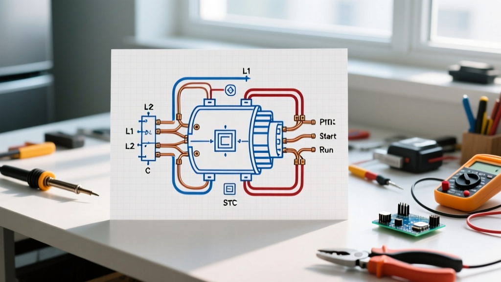
The compressor dome features three glass-to-metal seal pins. Identifying these correctly is the foundation of reading any wiring diagram for refrigerator compressor setups:
- Common (C): The shared return path for both the start and run windings. This pin connects to the main power neutral via the overload protector.
- Start (S): Connects to the start winding, which provides the initial phase-shifted torque to break the rotor's inertia.
- Run (R): Connects to the run winding, which sustains the motor's rotation and operates at a lower resistance than the start winding.
2. PTC Start Relay and Overload Protector (OLP)
Modern units (2010-present) utilize a Positive Temperature Coefficient (PTC) thermistor relay rather than the older current-type electromagnetic relays. The PTC allows high current to flow to the start winding upon startup, heats up in milliseconds, and increases its resistance to effectively drop the start winding out of the circuit. The OLP is a bimetallic thermal switch wired in series with the Common terminal to cut power if the compressor overheats or draws excessive Locked Rotor Amps (LRA).
Terminal Resistance Matrix: Verifying the Motor Windings
Before connecting any wires, you must verify the integrity of the internal motor windings using a digital multimeter. Below is the expected resistance matrix for a standard 1/4 HP compressor, such as the widely used Embraco EMU75HLC or Secop (Danfoss) TLES8.7KK.3.
| Measurement Path | Expected Resistance (Ohms) | Diagnostic Meaning |
|---|---|---|
| Common to Run (C-R) | 4.0 Ω - 6.0 Ω | Run winding integrity (lowest resistance) |
| Common to Start (C-S) | 10.0 Ω - 15.0 Ω | Start winding integrity (higher resistance) |
| Start to Run (S-R) | 14.0 Ω - 21.0 Ω | Sum of C-R and C-S (verifies no open circuits) |
| Any Pin to Copper Dome | Infinite (OL) | Verifies no short to ground (must be infinite) |
Expert Insight: If your S-R reading is not exactly equal to the sum of your C-R and C-S readings, the internal windings are compromised with a partial short. Do not proceed with installation; the compressor is defective.
Pre-Installation Planning and NEC Compliance
Electrical safety is non-negotiable. According to the National Fire Protection Association (NFPA), refrigeration equipment wiring must comply with NEC Article 440 (Air-Conditioning and Refrigerating Equipment). Furthermore, strict adherence to OSHA Lockout/Tagout (LOTO) procedures is required before touching the terminal block.
Wire Gauge and Harness Selection
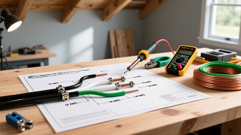
The branch circuit supplying the refrigerator should be a dedicated 15A or 20A, 120V circuit wired with 14 AWG or 12 AWG copper Romex. However, the internal harness connecting the main control board to the compressor requires specific attention:
- Gauge: 18 AWG stranded copper.
- Insulation Rating: Minimum 105°C (221°F). Standard PVC wire will melt when routed near the discharge line. Use SJOOW cordage or high-temp THHN.
- Connectors: Fully insulated 1/4" female spade disconnects. Never use non-insulated crimps near the grounded steel compressor dome.
Step-by-Step Wiring Sequence
Follow this exact sequence to ensure proper phase alignment and thermal protection.
- Prep the Harness: Strip 1/4 inch of insulation from the 18 AWG wires. Crimp using a ratcheting crimper (e.g., Klein Tools 1005) to ensure a gas-tight connection on the spade terminals.
- Install the Overload Protector (OLP): Slide the OLP onto the Common (C) terminal. This is critical; placing the OLP on the Start or Run terminal will bypass thermal protection for the main winding.
- Mount the PTC Relay: Align the PTC relay slots with the Start (S) and Run (R) terminals. Push firmly until it seats flush against the compressor housing.
- Connect the Harness: Plug the Neutral (White) wire into the OLP spade. Plug the Line (Black/Hot) wire into the Run terminal spade on the PTC relay. (Note: Some PTC relays have a dedicated Line input slot; follow the specific manufacturer schematic printed on the relay housing).
- Secure the Earth Ground: Attach the bare or green ground wire to the designated grounding screw on the compressor mounting bracket or the chassis ground lug. Never ground to the copper refrigerant lines.
Troubleshooting Common Wiring Failures
Even with a perfect wiring diagram for refrigerator compressor systems, field conditions introduce variables. Use this diagnostic matrix if the unit fails to start post-installation.
| Symptom | Probable Failure Mode | Diagnostic Action |
|---|---|---|
| Clicks, hums for 3 seconds, then clicks off. | Seized rotor or failed PTC relay. | Shake the PTC relay. If it rattles like a maraca, the internal thermistor disc has shattered. Replace the relay. |
| Compressor is dead silent; no vibration. | Open circuit in Common line or tripped OLP. | Test OLP for continuity. If open, allow 15 minutes to cool. If it remains open, replace the OLP. |
| Compressor runs but trips GFCI/AFCI breaker. | Short to ground or moisture in the terminal box. | Megger test the compressor windings to ground at 500V. Ensure the terminal cover gasket is sealed. |
2026 Parts Sourcing and Cost Expectations
When planning your installation budget, factor in the cost of high-quality OEM or premium aftermarket electrical components. Cheap, unbranded relays often fail within months due to substandard PTC ceramic discs.
- OEM Secop / Danfoss PTC Relay: $18.00 - $26.00 (Direct replacement, highest reliability).
- Supco RCO810 Hard Start Kit: $38.00 - $48.00 (Includes a heavy-duty PTC and a 15µF run capacitor; ideal for older units experiencing low-voltage brownouts or high head-pressure starts).
- Universal 18 AWG High-Temp Harness: $12.00 - $15.00 per pre-assembled pigtail set.
For broader context on appliance efficiency and how electrical faults impact overall energy consumption, refer to the U.S. Department of Energy's Energy Saver guidelines. A compressor struggling through a high-resistance wiring connection can increase the unit's kWh draw by up to 14%, silently inflating utility bills while degrading the motor insulation.
Final Verification
Before reinstalling the cardboard or plastic terminal cover, double-check that no stray wire strands are bridging the gap between the Run and Start terminals. Reapply the terminal cover to prevent dust accumulation and moisture ingress, which are the leading causes of terminal arcing in humid environments. Once the vacuum holds at 500 microns and the system is charged, energize the circuit and verify the running amp draw settles within the Rated Load Amps (RLA) stamped on the compressor nameplate.